THEFT DETERRENT / KEYLESS ENTRY SMART ENTRY AND START SYSTEM(for Start Function, Gasoline Model) B27841C Antenna Coil Circuit Voltage Out of Range
DESCRIPTION
When an open or short circuit is detected in the transponder key amplifier coil built into the engine switch, the certification ECU (smart key ECU assembly) stores this DTC. This DTC is also stored as a history DTC.
| DTC No. | Detection Item | DTC Detection Condition | Trouble Area | Note |
|---|---|---|---|---|
| B27841C | Antenna Coil Circuit Voltage Out of Range | The transponder key amplifier coil built into the engine switch is open (see below) or shorted (determined by communication with certification ECU (smart key ECU assembly)). (1 trip detection logic*) | ·
Engine switch ·
Certification ECU (smart key ECU assembly) ·
Wire harness or connector |
DTC output confirmation operation:
With the shift position in P and the electrical key transmitter sub-assembly held near the engine switch, an engine start operation is performed by pressing and holding the engine switch when the transmitter battery is depleted. |
*: Only output while a malfunction is present.
| Vehicle Condition when Malfunction Detected | Fail-safe Operation when Malfunction Detected |
|---|---|
| Engine cannot be started when transmitter battery is depleted by holding electrical key transmitter sub-assembly near engine switch and pressing and holding engine switch with shift position in P | - |
| DTC No. | Data List and Active Test |
|---|---|
| B27841C | - |
WIRING DIAGRAM
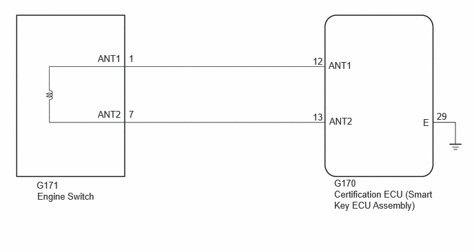
CAUTION / NOTICE / HINT
- NOTICE:
- ·
When using the GTS with the ignition switch off, connect the GTS to the DLC3 and turn a courtesy light switch on and off at intervals of 1.5 seconds or less until communication between the GTS and the vehicle begins. Then select Model Code "KEY REGIST" under manual mode and enter the following menus: Body Electrical / Smart Key. While using the GTS, periodically turn a courtesy light switch on and off at intervals of 1.5 seconds or less to maintain communication between the GTS and the vehicle.
·The smart entry and start system (for Start Function) uses the LIN communication system and CAN communication system. Inspect the communication function by following How to Proceed with Troubleshooting. Troubleshoot the smart entry and start system (for Start Function) after confirming that the communication systems are functioning properly.
·Before replacing the certification ECU (smart key ECU assembly), refer to Service Bulletin.
·After performing repairs, confirm that no DTCs are output by performing "DTC Output Confirmation Operation".
PROCEDURE
Check that the connectors are properly connected to the engine switch and certification ECU (smart key ECU assembly).
- OK:
Connectors are properly connected.
- Result:
Proceed to OK NG
OK
NG
Pre-procedure1
Disconnect the G170 certification ECU (smart key ECU assembly) connector.
Disconnect the G171 engine switch connector.
Procedure1
Measure the resistance according to the value(s) in the table below.
- Standard Resistance:
Tester Connection Condition Specified Condition G170-12 (ANT1) - G171-1 (ANT1) Always Below 1 Ω G170-12 (ANT1) or G171-1 (ANT1) - Other terminals and body ground Always 10 kΩ or higher G170-13 (ANT2) - G171-7 (ANT2) Always Below 1 Ω G170-13 (ANT2) or G171-7 (ANT2) - Other terminals and body ground Always 10 kΩ or higher
- Result:
Proceed to OK NG
Post-procedure1
Connect the G170 certification ECU (smart key ECU assembly) connector.
OK
NG
Using an oscilloscope, check the waveform.
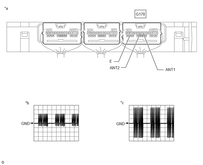
| *a | Component with harness connected
(Certification ECU (Smart Key ECU Assembly)) |
*b | Waveform 1 |
| *c | Waveform 2 | - | - |
- OK:
Tester Connection Condition Tool Setting Specified Condition G170-12 (ANT1) - G170-29 (E) Ignition switch off, electrical key transmitter sub-assembly not in cabin, within 30 seconds of engine switch pressed 5 V/DIV., 200 ms./DIV. Pulse generation
(See waveform 1)G170-13 (ANT2) - G170-29 (E) Ignition switch off, electrical key transmitter sub-assembly not in cabin, within 30 seconds of engine switch pressed 20 V/DIV., 200 ms./DIV. Pulse generation
(See waveform 2)
- Result:
Proceed to OK NG
OK
for M20C-FKS:
for M20D-FKS:
NG