RM36D0EC _58 Vehicle Interior _083095 LIGHTING (INT) _0400584 LIGHTING SYSTEM J

LIGHTING (INT)  LIGHTING SYSTEM  Interior Light Auto Cut Circuit  


DESCRIPTION

When the battery saving control operates, the main body ECU (multiplex network body ECU) controls the operation of the DOME CUT relay that is built into the power distribution box assembly to turn off the interior lights.

WIRING DIAGRAM
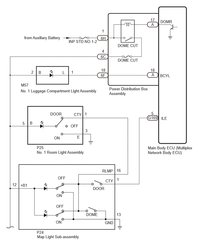
C394038E10
4.198,1.542 5.427,1.74 1.229,0.198 10 false DOME CUT 4.198,2.063 5.427,2.26 1.229,0.198 10 false DOME CUT 5.719,0.688 6.333,0.885 0.615,0.198 10 false DOMR 5.365,0.625 5.677,0.823 0.313,0.198 10 false 17 2.448,1.396 3.677,1.594 1.229,0.198 10 false INP STD NO.1-2 0.865,1.26 2.5,1.583 1.635,0.323 10 false from Auxiliary Battery 3.594,1.281 3.906,1.479 0.313,0.198 10 false 6H 3.635,1.021 3.792,1.219 0.156,0.198 10 false 1 3.896,3.083 5.333,3.49 1.438,0.406 10 false Power Distribution Box Assembly 3.594,1.938 3.906,2.135 0.313,0.198 10 false 6C 5.271,5.188 6.938,5.583 1.667,0.396 10 false Main Body ECU (Multiplex Network Body ECU) 5.406,2.583 5.719,2.802 0.313,0.219 10 false A 3.635,1.74 3.792,1.938 0.156,0.198 10 false 4 1.115,2.49 1.271,2.688 0.156,0.198 10 false 2 1.375,2.5 1.531,2.698 0.156,0.198 10 false B 2.229,2.5 2.385,2.698 0.156,0.198 10 false L 2.542,2.49 2.698,2.688 0.156,0.198 10 false 1 3.594,2.604 3.906,2.802 0.313,0.198 10 false 6F 3.604,2.417 3.917,2.615 0.313,0.198 10 false 18 5.708,2.615 6.323,2.813 0.615,0.198 10 false BCYL 5.365,2.417 5.677,2.615 0.313,0.198 10 false 18 5.396,0.792 5.708,0.99 0.313,0.198 10 false A 5.281,4.115 5.896,4.313 0.615,0.198 10 false G169 5.75,4.135 6.365,4.333 0.615,0.198 10 false ILE 5.396,3.958 5.552,4.156 0.156,0.198 10 false 5 0.74,3.156 3.646,3.354 2.906,0.198 10 false No. 1 Luggage Compartment Light Assembly 0.75,2.948 1.063,3.146 0.313,0.198 10 false M57 1.313,5.344 4.219,5.542 2.906,0.198 10 false No. 1 Room Light Assembly 1.313,5.177 1.625,5.375 0.313,0.198 10 false P25 1.063,4.302 1.219,4.5 0.156,0.198 10 false B 0.802,4.313 1.073,4.604 0.271,0.292 10 false 5 2.635,4 3.25,4.198 0.615,0.198 10 false CTY 1.792,3.979 2.406,4.177 0.615,0.198 10 false DOOR 2.521,4.406 3.135,4.604 0.615,0.198 10 false OFF 2.75,4.802 2.906,5 0.156,0.198 10 false E 1.927,4.833 2.24,5.031 0.313,0.198 10 false ON 3.021,3.979 3.177,4.177 0.156,0.198 10 false 1 3.042,4.573 3.198,4.771 0.156,0.198 10 false 3 3.76,6.365 4.375,6.563 0.615,0.198 10 false CTY 4.156,7.563 4.469,7.76 0.313,0.198 10 false 13 0.729,6.521 1.344,6.719 0.615,0.198 10 false +B1 0.438,6.5 0.75,6.698 0.313,0.198 10 false 12 2.063,6.26 2.677,6.458 0.615,0.198 10 false OFF 2,7.271 2.615,7.469 0.615,0.198 10 false OFF 2.01,6.885 2.323,7.083 0.313,0.198 10 false ON 1.99,7.833 2.302,8.031 0.313,0.198 10 false ON 3.313,6.635 3.927,6.833 0.615,0.198 10 false DOOR 3.073,7.563 3.688,7.76 0.615,0.198 10 false DOME 3.74,7.854 4.354,8.052 0.615,0.198 10 false GND 4.167,6.313 4.323,6.51 0.156,0.198 10 false 1 1.313,8.198 1.625,8.396 0.313,0.198 10 false P24 1.323,8.354 4.229,8.552 2.906,0.198 10 false Map Light Sub-assembly 4.156,5.99 4.469,6.25 0.313,0.26 10 false 16 3.646,6.01 4.26,6.208 0.615,0.198 10 false RLMP

C394037E07
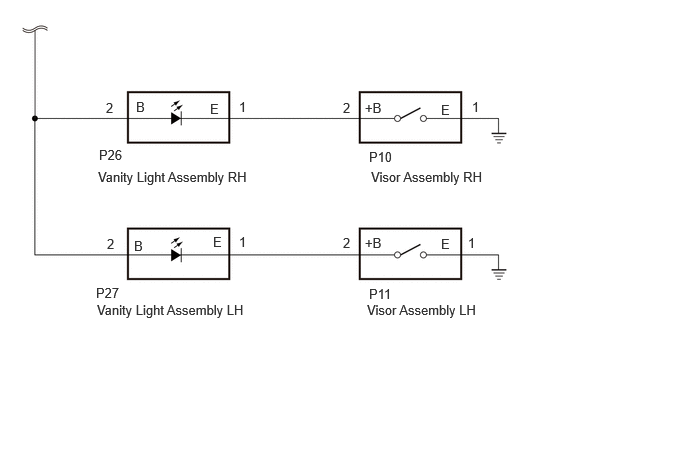
1.417,1.031 1.573,1.229 0.156,0.198 10 false B 1.396,2.479 1.552,2.677 0.156,0.198 10 false B 2.188,1.052 2.344,1.25 0.156,0.198 10 false E 2.219,2.438 2.302,2.604 0.083,0.167 10 false E 1.021,1.76 3.625,1.958 2.604,0.198 10 false Vanity Light Assembly RH 1.01,3.146 3.615,3.344 2.604,0.198 10 false Vanity Light Assembly LH 3.865,1.76 5.396,1.958 1.531,0.198 10 false Visor Assembly RH 3.823,3.146 5.354,3.344 1.531,0.198 10 false Visor Assembly LH 1.031,1.531 2.281,1.729 1.25,0.198 10 false P26 1,2.969 1.875,3.177 0.875,0.208 10 false P27 3.844,1.552 4.302,1.75 0.458,0.198 10 false P10 3.844,2.979 4.302,3.177 0.458,0.198 10 false P11 1.104,1.042 1.635,1.229 0.531,0.188 10 false 2 2.49,1.031 3.177,1.281 0.688,0.25 10 false 1 4.917,1.031 5.073,1.229 0.156,0.198 10 false 1 1.115,2.458 1.656,2.656 0.542,0.198 10 false 2 3.573,1.042 3.729,1.24 0.156,0.198 10 false 2 3.573,2.448 3.729,2.646 0.156,0.198 10 false 2 4.875,2.448 5.031,2.646 0.156,0.198 10 false 1 2.49,2.438 3.167,2.698 0.677,0.26 10 false 1 3.802,2.448 4.26,2.646 0.458,0.198 10 false +B 3.802,1.042 4.26,1.24 0.458,0.198 10 false +B 4.594,1.063 4.75,1.26 0.156,0.198 10 false E 4.594,2.458 4.75,2.656 0.156,0.198 10 false E

CAUTION / NOTICE / HINT

NOTICE:
·

Inspect the fuses for circuits related to this system before performing the following procedure.

·

Before replacing the main body ECU (multiplex network body ECU), refer to Service Bulletin.


PROCEDURE

1.CHECK VEHICLE CONDITION
a.

Check the vehicle condition.


Result:
Result Proceed to
All interior illumination supplied power to by DOME CUT relay does not turn on. A
All interior illumination supplied power to by DOME CUT relay does not turn off. B


A

2.CHECK HARNESS AND CONNECTOR (VANITY LIGHT ASSEMBLY RH - POWER DISTRIBUTION BOX ASSEMBLY)

B

4.PERFORM ACTIVE TEST USING GTS
2.CHECK HARNESS AND CONNECTOR (VANITY LIGHT ASSEMBLY RH - POWER DISTRIBUTION BOX ASSEMBLY)
a.

Disconnect the P26 vanity light assembly RH connector.


b.

Disconnect the P27 vanity light assembly LH connector.


c.

Disconnect the M57 No. 1 luggage compartment light assembly connector.


d.

Disconnect the P24 map light sub-assembly connector.


e.

Disconnect the P25 No. 1 room light assembly connector.


f.

Disconnect the 6C power distribution box assembly connector.


g.

Measure the resistance according to the value(s) in the table below.

Standard Resistance:
Tester Connection Condition Specified Condition
P26-2 (B) - 6C-4 Always Below 1 Ω
P26-2 (B) or 6C-4 - Body ground Always 10 kΩ or higher


Result:
Proceed to
OK
NG


OK

3.CHECK HARNESS AND CONNECTOR (POWER DISTRIBUTION BOX ASSEMBLY - AUXILIARY BATTERY)

NG

REPAIR OR REPLACE HARNESS OR CONNECTOR

3.CHECK HARNESS AND CONNECTOR (POWER DISTRIBUTION BOX ASSEMBLY - AUXILIARY BATTERY)
a.
E443709C08
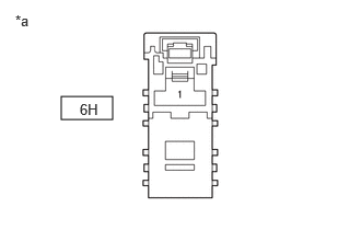
0.583,0.917 1.073,1.135 0.49,0.219 0.146,0.115 0.458,0.271 0.313,0.156 10 false *a 0.76,0.958 1.073,1.115 0.313,0.156 10 false 6H
*a Front view of wire harness connector
(to Power Distribution Box Assembly)


Disconnect the power distribution box assembly connector.


b.

Measure the voltage according to the value(s) in the table below.

Standard Voltage:
Tester Connection Switch Condition Specified Condition
6H-1 - Body ground Ignition switch off 11 to 14 V


Result:
Proceed to
OK
NG


OK

5.CHECK POWER DISTRIBUTION BOX ASSEMBLY

NG

REPAIR OR REPLACE HARNESS OR CONNECTOR

4.PERFORM ACTIVE TEST USING GTS
a.

Perform the Active Test according to the display on the GTS.

Body Electrical > Main Body > Active Test
Tester Display Measurement Item Control Range Diagnostic Note
Relay for Interior Light Auto Cut Function DOME CUT relay OFF or ON When performing this Active Test, turn all the interior lights on.
·

OFF: DOME CUT relay on (interior lights turn on)

·

ON: DOME CUT relay off (interior lights turn off)


Body Electrical > Main Body > Active Test
Tester Display
Relay for Interior Light Auto Cut Function
50004 449 27
OK:

All of the interior lights turn off when ON is selected.


Result:
Proceed to
OK
NG


OK

NG

5.CHECK POWER DISTRIBUTION BOX ASSEMBLY
a.

Remove the power distribution box assembly.
Click herePower Source / Network>POWER DISTRIBUTION>MAIN BODY ECU>REMOVAL

E443710C08
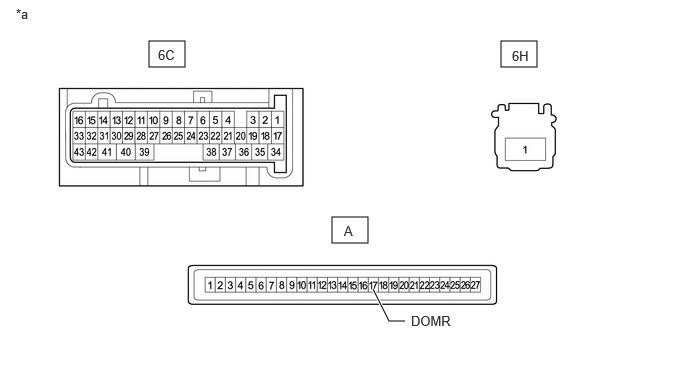
1.552,0.427 1.927,0.698 0.375,0.271 5.219,0.427 5.594,0.698 0.375,0.271 3.458,2.26 3.833,2.531 0.375,0.271 4.219,3.344 4.052,3.344 4.052,3.344 3.885,3.01 true 0.167,0.063 0.479,0.219 0.313,0.156 10 false *a 5.333,0.5 5.646,0.698 0.313,0.198 10 false 6H 1.646,0.49 1.958,0.688 0.313,0.198 10 false 6C 3.583,2.323 3.74,2.521 0.156,0.198 10 false A 4.281,3.26 4.896,3.458 0.615,0.198 10 false DOMR
*a Component without harness connected
(Power Distribution Box Assembly)
- -


b.

Remove the main body ECU (multiplex network body ECU) from the power distribution box assembly.

Click herePower Source / Network>POWER DISTRIBUTION>MAIN BODY ECU>REMOVAL


c.

Measure the resistance according to the value(s) in the table below.

Standard Resistance:
Tester Connection Condition Specified Condition
6C-6 - 6H-1 Auxiliary battery not connected to 6H-1 and A-17 (DOMR) 10 kΩ or higher


d.

Measure the voltage according to the value(s) in the table below.

Standard Voltage:
Tester Connection Condition Specified Condition
6C-6 - Auxiliary battery negative (-) terminal Auxiliary battery positive (+) → 6H-1
Auxiliary battery negative (-) → A-17 (DOMR)
11 to 14 V
Auxiliary battery not connected to 6H-1 and A-17 (DOMR) Below 1 V


Result:
Proceed to
OK
NG


OK

NG