STOP AND START STOP AND START SYSTEM TERMINALS OF ECU
ENGINE STOP AND START ECU
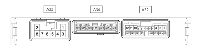
Disconnect the engine stop and start ECU connectors.
Measure the resistance and voltage according to the value(s) in the table below.
| Terminal No. (Symbol) | Wiring Color | Terminal Description | Condition | Specified Condition |
|---|---|---|---|---|
| A33-1 (BIN2) - Body ground | W - Body ground | Battery | Always | 9.5 to 14 V |
| A33-2 (GND2) - Body ground | W-B - Body ground | Ground | Always | Below 1 Ω |
| A33-3 (BIN1) - Body ground | B - Body ground | Battery | Always | 9.5 to 14 V |
| A33-8 (GND1) - Body ground | W-B - Body ground | Ground | Always | Below 1 Ω |
| A34-1 (+B) - Body ground | R - Body ground | Power source of engine stop and start ECU | Ignition switch ON | 9.5 to 14 V |
| A34-6 (DGND) - Body ground | W-B - Body ground | Ground | Always | Below 1 Ω |
| A34-10 (NE) - Body ground | BR - Body ground | Engine speed signal from ECM | Always | 10 kΩ or higher |
| A32-13 (CANH) - Body ground | R - Body ground | CAN communication | Always | 200 Ω or higher |
| A32-14 (CANL) - Body ground | W - Body ground | CAN communication | Always | 200 Ω or higher |
| A32-18 (IGP) - Body ground | GR - Body ground | Ignition switch signal | Ignition switch ON | 9.5 to 14 V |
| A32-19 (ACC) - Body ground | G - Body ground | Ignition switch signal | Ignition switch ACC | 9.5 to 14 V |
| A32-21 (IGR) - Body ground | R - Body ground | Ignition switch signal | Ignition switch ON | 9.5 to 14 V |
Reconnect the engine stop and start ECU connectors.
Measure the resistance, voltage and pulse according to the value(s) in the table below.
| Terminal No. (Symbol) | Wiring Color | Terminal Description | Condition | Specified Condition |
|---|---|---|---|---|
| A33-6 (OP21) - A34-6 (DGND) | GR - W-B | Oil pump with motor assembly drive power source signal | One of the following conditions is met:
·
Engine stopped by stop and start system control ·
Ignition switch ON (engine not running) and Active Test "Oil Pump" being performed |
10.5 to 16 V |
| A34-3 (BRE2) - Body ground | V - Body ground | Ground (vacuum sensor assembly) | Always | Below 1 Ω |
| A34-7 (BNT1) - A34-6 (DGND) | Y - W-B | Engine hood courtesy switch (hood lock assembly) signal | ·
Ignition switch ON ·
Engine stopped ·
Engine hood closed |
Below 1.5 V |
·
Ignition switch ON ·
Engine stopped ·
Engine hood open |
8 to 14 V | |||
| A34-9 (OPM1) - A34-6 (DGND) | R - W-B | Oil pump with motor assembly directions signal | One of the following conditions is met:
·
Engine stopped by stop and start system control ·
Ignition switch ON (engine not running) and Active Test "Oil Pump" being performed |
Pulse generation
(See waveform 1) |
| A34-10 (NE) - A34-6 (DGND) | BR - W-B | Engine speed signal from ECM | Idling after engine warmed up | Pulse generation
(See waveform 2) |
| A34-13 (PB) - A34-3 (BRE2) | SB - V | Vacuum sensor assembly signal | ·
Ignition switch ON ·
Absolute pressure of 40 kPa (300 mmHg, 11.8 in.Hg) applied to vacuum sensor assembly |
1.6 to 2.0 V |
·
Ignition switch ON ·
Absolute pressure of 60 kPa (450 mmHg, 17.7 in.Hg) applied to vacuum sensor assembly |
2.2 to 2.6 V | |||
·
Ignition switch ON ·
Atmospheric pressure applied to vacuum sensor assembly |
3.4 to 3.8 V | |||
| A34-14 (BRVC) - A34-6 (DGND) | W - W-B | Vacuum sensor assembly power supply | ·
Ignition switch ON ·
Engine stopped |
4.5 to 5.5 V |
| A34-21 (STA) - A34-6 (DGND) | LG - W-B | Starter pinion operation signal | Cranking | 6.0 V or more |
| A34-27 (NOPM) - A34-6 (DGND) | LG - W-B | Oil pump with motor assembly speed signal | One of the following conditions is met:
·
Engine stopped by stop and start system control ·
Ignition switch ON (engine not running) and Active Test "Oil Pump" being performed |
Pulse generation
(See waveform 3) |
| A32-1 (IG31) - A34-6 (DGND) | SB - W-B | Backup boost converter signal | Ignition switch ON | 10.5 to 16 V |
| A32-2 (B41) - A34-6 (DGND) | LA-L - W-B | Backup boost converter signal | Always | 10.5 to 16 V |
| A32-3 (IG41) - A34-6 (DGND) | L - W-B | Backup boost converter signal | Ignition switch ON | 10.5 to 16 V |
| A32-5 (ECAN) - A34-6 (DGND) | V - W-B | Stop and start system cancel switch (eco run cancel switch assembly) signal | ·
Ignition switch ON ·
Stop and start system cancel switch (eco run cancel switch assembly) pressed |
Below 1.5 V |
·
Ignition switch ON ·
Stop and start system cancel switch (eco run cancel switch assembly) not pressed |
8 to 14 V | |||
| A32-10 (IG12) - A34-6 (DGND) | W - W-B | Backup boost converter signal | Ignition switch ON | 10.5 to 16 V |
| A32-12 (B42) - A34-6 (DGND) | LA-B - W-B | Backup boost converter signal | Always | 10.5 to 16 V |
| A32-18 (IGP) - A34-6 (DGND) | GR - W-B | Ignition switch signal | Ignition switch ACC | Below 1 V |
| Ignition switch ON | 9.5 to 14 V | |||
| A32-19 (ACC) - A34-6 (DGND) | G - W-B | Ignition switch signal | Ignition switch off | Below 1 V |
| Ignition switch ACC | 9.5 to 14 V | |||
| A32-21 (IGR) - A34-6 (DGND) | R - W-B | Ignition switch signal | Ignition switch ACC | Below 1 V |
| Ignition switch ON | 9.5 to 14 V | |||
| A32-26 (AC42) - A34-6 (DGND) | BE - W-B | Backup boost converter signal | Ignition switch ACC | 10.5 to 16 V |
| A32-25 (IL41) - A34-6 (DGND) | Y - W-B | Backup boost converter signal | Headlight dimmer switch (light control switch) in tail or head position | 10.5 to 16 V |
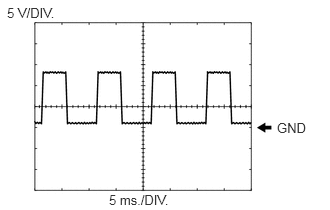
Waveform 1
| Item | Content |
|---|---|
| Tester Connection | A34-9 (OPM1) - A34-6 (DGND) |
| Tool Setting | 5 V/DIV., 5 ms./DIV. |
| Condition | One of the following conditions is met:
·
Engine stopped by stop and start control ·
Ignition switch ON (engine not running) and Active Test "Oil Pump" being performed |
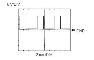
Waveform 2
| Item | Content |
|---|---|
| Tester Connection | A34-10 (NE) - A34-6 (DGND) |
| Tool Setting | 5 V/DIV., 2 ms./DIV. |
| Condition | Idling after engine warmed up |
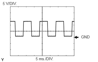
Waveform 3
| Item | Content |
|---|---|
| Tester Connection | A34-27 (NOPM) - A34-6 (DGND) |
| Tool Setting | 5 V/DIV., 5 ms./DIV. |
| Condition | One of the following conditions is met:
·
Engine stopped by stop and start control ·
Ignition switch ON (engine not running) and Active Test "Oil Pump" being performed |