☰ Toyota RAV4☰ فهرستAudio / Visual / Telematics › PARK ASSIST / MONITORING › PANORAMIC VIEW MONITOR SYSTEM
RM36D0EC
_56
Audio / Visual / Telematics
_083082
PARK ASSIST / MONITORING
_0586733
PANORAMIC VIEW MONITOR SYSTEM
J
PARK ASSIST / MONITORING PANORAMIC VIEW MONITOR SYSTEM ECU Power Source Circuit
DESCRIPTION
This circuit is the power source circuit to operate the parking assist ECU. The parking assist ECU controls the panoramic view monitor system.
WIRING DIAGRAM
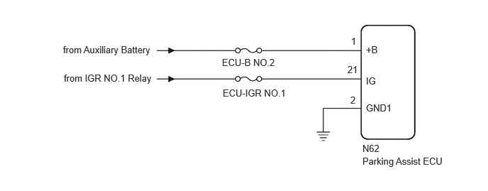
5.323,2.281 7.156,2.594
1.833,0.313
10
false
Parking Assist ECU
5.323,2.094 7.156,2.406
1.833,0.313
10
false
N62
0.927,0.646 2.76,0.958
1.833,0.313
10
false
from Auxiliary Battery
0.938,1.063 3.188,1.396
2.25,0.333
10
false
from IGR NO.1 Relay
3.26,0.833 5.094,1.146
1.833,0.313
10
false
ECU-B NO.2
3.271,1.281 5.104,1.594
1.833,0.313
10
false
ECU-IGR NO.1
5.375,1.104 7.156,1.417
1.781,0.313
10
false
IG
5.375,1.5 7.156,1.813
1.781,0.313
10
false
GND1
5.375,0.646 7.156,0.958
1.781,0.313
10
false
+B
5.156,0.521 6.938,0.833
1.781,0.313
10
false
1
5.104,0.938 6.885,1.25
1.781,0.313
10
false
21
5.146,1.385 6.927,1.698
1.781,0.313
10
false
2
CAUTION / NOTICE / HINT
- NOTICE:
- ·
Depending on the parts that are replaced or operations that are performed during vehicle inspection or maintenance, calibration of other systems as well as the panoramic view monitor system may be needed.
·Inspect the fuse for circuits related to this system before performing the following procedure.
PROCEDURE
1.CHECK HARNESS AND CONNECTOR (PARKING ASSIST ECU - BATTERY AND BODY GROUND)
a.
Disconnect the N62 parking assist ECU connector.
b.
Measure the resistance according to the value(s) in the table below.
- Standard Resistance:
Tester Connection Condition Specified Condition N62-2 (GND1) - Body ground Always Below 1 Ω
c.
Measure the voltage according to the value(s) in the table below.
- Standard Voltage:
Tester Connection Switch Condition Specified Condition N62-1 (+B) - N62-2 (GND1) Ignition switch off 11 to 14 V N62-21 (IG) - N62-2 (GND1) Ignition switch ON 11 to 14 V Ignition switch off Below 1 V
- Result:
Proceed to OK NG
OK
PROCEED TO NEXT SUSPECTED AREA SHOWN IN PROBLEM SYMPTOMS TABLE
NG
REPAIR OR REPLACE HARNESS OR CONNECTOR