K121F CVT CONTINUOUSLY VARIABLE TRANSAXLE SYSTEM P172A7E Starter Enable Relay Actuator Stuck On
DESCRIPTION
When the shift lever is in P or N, the ECM sends the shift state signal to the certification ECU (smart key ECU assembly).
Certification ECU (smart key ECU assembly) operates the starter assembly only when the shift lever is in P or N.
| DTC No. | Detection Item | DTC Detection Condition | Trouble Area | MIL | DTC Output from | Priority | Note |
|---|---|---|---|---|---|---|---|
| P172A7E | Starter Enable Relay Actuator Stuck On | All of the following conditions are met for 0.3 seconds or more (1-trip detection logic):
·
Within 3 seconds after engine start ·
The shift lever is in other than P or N and the stop and start system is not operating ·
The starter signal is ON |
·
Certification ECU (Smart key ECU assembly) ·
Wire harness or connector ·
ECM |
Does not come on | Engine | B | SAE Code:
P172B |
MONITOR DESCRIPTION
When the ECM has not given permission for starter operation and a starter signal is received, the ECM detects the malfunction and stores this DTC.
CONFIRMATION DRIVING PATTERN
- NOTICE:
-
Perform the confirmation driving pattern with the AUTO function (shift-linked function) of the electric parking brake system off.
- HINT:
-
After repairs have been completed, clear the DTCs and then check that the vehicle has returned to normal by performing the following All Readiness check procedure.
Clear the DTCs (even if no DTCs are stored, perform the clear DTC procedure).
Turn the ignition switch off and wait for 2 minutes or more.
Fully apply the parking brake and chock all 4 wheels.
- HINT:
-
When the parking brake indicator (red) is illuminated after the electric parking brake switch (integration control and panel assembly) has been pulled to the lock side, the maximum amount of braking force is applied if the electric parking brake switch (integration control and panel assembly) is pulled to the lock side one more time.
Keep your left foot firmly on the brake pedal and move the shift lever to R.
Turn the ignition switch on (Start).
Keep your left foot firmly on the brake pedal and move the shift lever to D.
Turn the ignition switch on (Start).
Enter the following menus: Powertrain / Engine / Utility / All Readiness.
Input the DTC: P172A7E.
Check the DTC judgment result.
| GTS Display | Description |
|---|---|
| NORMAL | ·
DTC judgment completed ·
System normal |
| ABNORMAL | ·
DTC judgment completed ·
System abnormal |
| INCOMPLETE | ·
DTC judgment not completed ·
Perform driving pattern after confirming DTC enabling conditions |
| N/A | ·
Unable to perform DTC judgment ·
Number of DTCs which do not fulfill DTC preconditions has reached ECU memory limit |
- HINT:
- ·
If the judgment result shows NORMAL, the system is normal.
·If the judgment result shows ABNORMAL, the system has a malfunction.
·If the judgment result shows INCOMPLETE or N/A, perform the Confirmation Driving Pattern and check the DTC judgment result again.
WIRING DIAGRAM
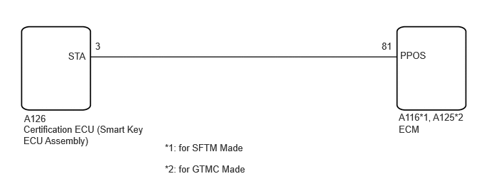
CAUTION / NOTICE / HINT
- NOTICE:
- ·
Perform registration and/or initialization when parts related to the continuously variable transaxle system are replaced.
·Check that no DTCs are stored after performing initialization.
- HINT:
-
If any DTCs other than P172A7E are output, perform troubleshooting for those DTCs first.
PROCEDURE
Using the GTS, perform a Health Check.
- Result:
Result Proceed to Only P172A7E is output A P172A7E and other DTCs are output B
A
B
Pre-procedure1
Disconnect the A126 smart key ECU assembly connector.
Turn the ignition switch to ON.
Procedure1
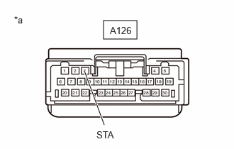
| *a | Front view of wire harness connector (to smart key ECU assembly) |
Measure the voltage according to the value(s) in the table below.
- Standard Voltage:
Tester Connection Condition Specified Condition A126-3 (STA) - Body ground Ignition switch ON, shift lever in P or N 11 to 14 V A126-3 (STA) - Body ground Ignition switch ON, shift lever not in P or N Below 1 V
- Result:
Proceed to OK NG
Post-procedure1
Turn the ignition switch off.
Connect the A126 smart key ECU assembly connector.
OK
NG
Pre-procedure1
Disconnect the A126 smart key ECU assembly connector.
for SFTM Made:
Disconnect the A116 ECM connector.
for GTMC Made:
Disconnect the A125 ECM connector.
Procedure1
Measure the resistance according to the value(s) in the table below.
- Standard Resistance (for SFTM Made):
Tester Connection Condition Specified Condition A126-3 (STA) or A116-81 (PPOS) - Other terminals Always 10 kΩ or higher
- Standard Resistance (for GTMC Made):
Tester Connection Condition Specified Condition A126-3 (STA) or A125-81 (PPOS) - Other terminals Always 10 kΩ or higher
- Result:
Proceed to OK NG
Post-procedure1
for SFTM Made:
Connect the A116 ECM connector.
for GTMC Made:
Connect the A125 ECM connector.
Connect the A126 smart key ECU assembly connector.
OK
NG
- HINT:
-
for M20C-FKS:
-
for M20D-FKS:
- Result:
Proceed to NEXT
NEXT
for Registration: Click hereDrivetrain>K121F (CVT)>CONTINUOUSLY VARIABLE TRANSAXLE SYSTEM>REGISTRATION202304,999999,_52,_138817,_0596468,RM100000002AWR8,
for Initialization: Click hereDrivetrain>K121F (CVT)>CONTINUOUSLY VARIABLE TRANSAXLE SYSTEM>INITIALIZATION202409,999999,_52,_138817,_0596468,RM100000002NRBH,