LIGHTING (EXT) LIGHTING SYSTEM High Beam Headlight Circuit
DESCRIPTION
The main body ECU (multiplex network body ECU) controls the high beam headlights.
WIRING DIAGRAM
for Triple Beam Headlight
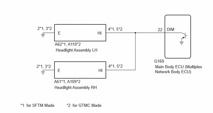
for Single Beam Headlight
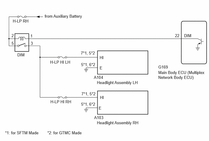
CAUTION / NOTICE / HINT
- NOTICE:
- ·
for Single Beam Headlight
Inspect the fuses for circuits related to this system before performing the following procedure.
·Check the operation of the low beam headlights. If the low beam headlights do not operate normally, refer to Problem Symptoms Table.
·Before replacing the main body ECU (multiplex network body ECU), refer to Service Bulletin.
PROCEDURE
Perform the Active Test according to the display on the GTS.
- Body Electrical > Main Body > Active Test
-
Tester Display Measurement Item Control Range Diagnostic Note High Beam Headlight High beam headlights OFF or ON -
- Body Electrical > Main Body > Active Test
-
Tester Display High Beam Headlight - 50004 449 52
- OK:
High beam headlights illuminate.
- Result:
Result Proceed to OK A NG (for Triple Beam Headlight) B NG (for Single Beam Headlight) C
A
B
C
*1: for SFTM Made
*2: for GTMC Made
Disconnect the G169 main body ECU (multiplex network body ECU) connector.
Disconnect the A62*1 or A110*2 headlight assembly LH connector.
Disconnect the A61*1 or A109*2 headlight assembly RH connector.
Measure the resistance according to the value(s) in the table below.
- Standard Resistance:
for SFTM Made Tester Connection Condition Specified Condition G169-22 (DIM) - A62-4 (HI) Always Below 1 Ω G169-22 (DIM) or A62-4 (HI) - Body ground Always 10 kΩ or higher
for GTMC Made Tester Connection Condition Specified Condition G169-22 (DIM) - A110-5 (HI) Always Below 1 Ω G169-22 (DIM) or A110-5 (HI) - Body ground Always 10 kΩ or higher
- Result:
Proceed to OK NG
OK
NG
- Result:
Proceed to OK NG
OK
NG
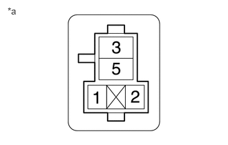
| *a | Front view of wire harness connector
(to DIM Relay) |
Remove the DIM relay.
Measure the voltage according to the value(s) in the table below.
- Standard Voltage:
Tester Connection Switch Condition Specified Condition 2 (DIM relay) - Body ground Ignition switch off 11 to 14 V 5 (DIM relay) - Body ground Ignition switch off 11 to 14 V
- Result:
Proceed to OK NG
OK
NG
Remove the DIM relay.
Disconnect the A103 headlight assembly RH connector.
Disconnect the A104 headlight assembly LH connector.
Measure the resistance according to the value(s) in the table below.
- Standard Resistance:
for SFTM Made Tester Connection Condition Specified Condition 3 (DIM relay) - A103-7 (HI) Always Below 1 Ω 3 (DIM relay) or A103-7 (HI) - Body ground Always 10 kΩ or higher
for GTMC Made Tester Connection Condition Specified Condition 3 (DIM relay) - A103-5 (HI) Always Below 1 Ω 3 (DIM relay) or A103-5 (HI) - Body ground Always 10 kΩ or higher
- Result:
Proceed to OK NG
OK
NG
Remove the DIM relay.
Disconnect the G169 main body ECU (multiplex network body ECU) connector.
Measure the resistance according to the value(s) in the table below.
- Standard Resistance:
Tester Connection Condition Specified Condition 1 (DIM relay) - G169-22 (DIM) Always Below 1 Ω 1 (DIM relay) or G169-22 (DIM) - Body ground Always 10 kΩ or higher
- Result:
Proceed to OK NG
OK
NG