LIGHTING (EXT) LIGHTING SYSTEM Front Fog Light Circuit
DESCRIPTION
The main body ECU (multiplex network body ECU) controls the front fog lights.
WIRING DIAGRAM

CAUTION / NOTICE / HINT
- NOTICE:
-
Inspect the fuses for circuits related to this system before performing the following procedure.
PROCEDURE
Using the GTS, read the Data List.
- Body Electrical > Power Distribution Box > Data List
-
Tester Display Measurement Item Range Normal Condition Diagnostic Note Front Fog Light External Relay Input Signal Front fog light switch input signal OFF or ON OFF: Front fog light switch off
ON: Front fog light switch on-
- Body Electrical > Power Distribution Box > Data List
-
Tester Display Front Fog Light External Relay Input Signal - 50003 475 1320
- OK:
Display changes according to the front fog light switch operation.
- Result:
Proceed to OK NG
OK
NG
Using the GTS, read the Data List.
- Body Electrical > Power Distribution Box > Data List
-
Tester Display Measurement Item Range Normal Condition Diagnostic Note Front Fog Light External Relay Output Signal Front fog light output condition OFF or ON OFF: Front fog light not illuminated
ON: Front fog light illuminated-
- Body Electrical > Power Distribution Box > Data List
-
Tester Display Front Fog Light External Relay Output Signal - 50003 475 1321
- OK:
Display changes according to the front fog light switch operation.
- Result:
Proceed to OK NG
OK
NG
- Result:
Proceed to OK NG
OK
NG
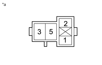
| *a | Front view of wire harness connector
(to FOG FR Relay) |
Remove the FOG FR relay.
Measure the voltage according to the value(s) in the table below.
- Standard Voltage:
Tester Connection Switch Condition Specified Condition 2 (FOG FR relay) - Body ground Ignition switch off 11 to 14 V 5 (FOG FR relay) - Body ground Ignition switch off 11 to 14 V
- Result:
Proceed to OK NG
OK
NG
*1: except Off Road Package
*2: for Off Road Package
Remove the FOG FR relay.
Disconnect the B18*1 or B11*2 fog light assembly LH connector.
Disconnect the B17*1 or B10*2 fog light assembly RH connector.
Disconnect the 6F power distribution box assembly connector.
Measure the resistance according to the value(s) in the table below.
- Standard Resistance:
except Off Road Package Tester Connection Condition Specified Condition 3 (FOG FR relay) - B17-2 (B) Always Below 1 Ω 3 (FOG FR relay) - B18-2 (B) Always Below 1 Ω 1 (FOG FR relay) - 6F-28 Always Below 1 Ω 3 (FOG FR relay) or B17-2 (B) - Body ground Always 10 kΩ or higher 3 (FOG FR relay) or B18-2 (B) - Body ground Always 10 kΩ or higher 1 (FOG FR relay) or 6F-28 - Body ground Always 10 kΩ or higher
for Off Road Package Tester Connection Condition Specified Condition 3 (FOG FR relay) - B10-2 (B) Always Below 1 Ω 3 (FOG FR relay) - B11-2 (B) Always Below 1 Ω 1 (FOG FR relay) - 6F-28 Always Below 1 Ω 3 (FOG FR relay) or B10-2 (B) - Body ground Always 10 kΩ or higher 3 (FOG FR relay) or B11-2 (B) - Body ground Always 10 kΩ or higher 1 (FOG FR relay) or 6F-28 - Body ground Always 10 kΩ or higher
- Result:
Proceed to OK NG
OK
NG