PARKING BRAKE ELECTRIC PARKING BRAKE SYSTEM(for Gasoline Model) Electric Parking Brake does not Operate
WIRING DIAGRAM
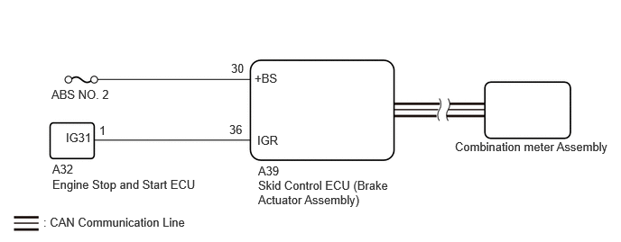
CAUTION / NOTICE / HINT
- NOTICE:
- ·
The electric parking brake may still operate up to 20 seconds after the ignition switch is turned off. Before disconnecting connectors or fuses, turn the ignition switch off and wait 20 seconds or more.
·Inspect the fuses for circuits related to this system before performing the following procedure.
·After replacing the skid control ECU (brake actuator assembly), perform acceleration sensor zero point calibration and store system information memorization.
·When replacing the skid control ECU (brake actuator assembly), operate the electric parking brake switch (integration control and panel assembly) as the parking brake indicator light blinks when the ignition switch is first turned to ON.
- HINT:
-
Even if the electric parking brake is operating normally, the parking brake indicator light on the combination meter may be malfunctioning.
PROCEDURE
Check if CAN communication system DTCs are output.
- Chassis > Brake/EPB > Trouble Codes
- 50001 435
- Result:
Result Proceed to DTCs are not output A DTCs are output B
A
B
for GTMC Made: Click herePower Source / Network>NETWORKING>CAN COMMUNICATION SYSTEM (for GTMC Made Gasoline Model)>HOW TO PROCEED WITH TROUBLESHOOTING202409,999999,_57,_083091,_0694856,RM100000002NTA4,
for SFTM Made: Click herePower Source / Network>NETWORKING>CAN COMMUNICATION SYSTEM (for SFTM Made Gasoline Model)>HOW TO PROCEED WITH TROUBLESHOOTING202409,999999,_57,_083091,_0694854,RM100000002NUBH,
With the wheels not contacting the ground, check the condition of the rear wheels when the electric parking brake is operating and not operating.
- Result:
Result Proceed to Lock and release operation is normal and parking brake indicator light turns off or blinks A Lock and release operation is malfunctioning and parking brake indicator light illuminates or turns off according to switch operation B Lock and release operation is malfunctioning and parking brake indicator light turns off or blinks C
A
B
C
Perform the Active Test of the combination meter assembly using the GTS.
- Body Electrical > Combination Meter > Active Test
-
Tester Display Park Warning - 50004 409 108
Check the combination meter assembly.
- OK:
Parking brake indicator light turns on or off in accordance with the GTS operation.
- Result:
Proceed to OK NG
OK
NG
for GTMC Made: Click hereVehicle Interior>METER / GAUGE / DISPLAY>METER / GAUGE SYSTEM (for GTMC Made)>HOW TO PROCEED WITH TROUBLESHOOTING202405,999999,_58,_083097,_0694857,RM100000002LUOC,
for SFTM Made: Click hereVehicle Interior>METER / GAUGE / DISPLAY>METER / GAUGE SYSTEM (for SFTM Made)>HOW TO PROCEED WITH TROUBLESHOOTING202405,999999,_58,_083097,_0694858,RM100000002LUR9,
Turn the ignition switch off.
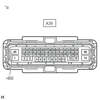
| *a | Front view of wire harness connector
(to Skid Control ECU (Brake Actuator Assembly)) |
Disconnect the A39 skid control ECU (brake actuator assembly) connector.
Measure the voltage according to the value(s) in the table below.
- Standard Voltage:
Tester Connection Condition Specified Condition A39-30 (+BS) - Body ground Ignition switch off 11 to 14 V
- Result:
Proceed to OK NG
OK
NG
Turn the ignition switch off.
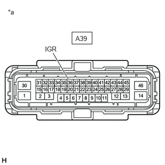
| *a | Front view of wire harness connector
(to Skid Control ECU (Brake Actuator Assembly)) |
Disconnect the A39 skid control ECU (brake actuator assembly) connector.
Measure the voltage according to the value(s) in the table below.
- Standard Voltage:
Tester Connection Condition Specified Condition A39-36 (IGR) - Body ground Ignition switch ON 10.5 to 16 V
- Result:
Proceed to OK NG
OK
NG
Turn the ignition switch off.
Disconnect the A39 skid control ECU (brake actuator assembly) connector.
Disconnect the A32 engine stop and start ECU connector.
Measure the resistance according to the value(s) in the table below.
- Standard Resistance:
Tester Connection Condition Specified Condition A39-36 (IGR) - A32-1 (IG31) Always Below 1 Ω A39-36 (IGR) or A32-1 (IG31) - Body ground Always 10 kΩ or higher
- Result:
Proceed to OK NG
OK
NG