GF2A TRANSFER / 4WD / AWD DYNAMIC TORQUE VECTORING AWD SYSTEM AWD Warning Light Remains ON
DESCRIPTION
The 4WD ECU assembly is connected to the combination meter assembly via the CAN communication system.
If the 4WD ECU assembly stores any DTCs which are related to the dynamic torque vectoring AWD system, the warning message is displayed on the multi-information display in the combination meter assembly.
WIRING DIAGRAM
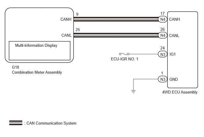
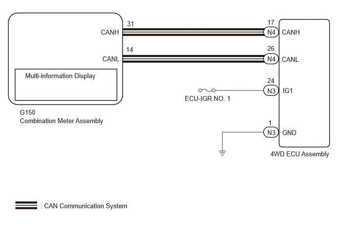
CAUTION / NOTICE / HINT
- NOTICE:
- ·
Inspect the fuses for circuits related to this system before performing the following inspection procedure.
·When the 4WD ECU assembly is replaced, before removing the 4WD ECU assembly, it is necessary to perform ECU Data Save to save the original 4WD ECU assembly information.
- HINT:
-
Check the condition of each related circuit connector before troubleshooting.
PROCEDURE
Connect the GTS to the DLC3.
Turn the engine switch on (IG).
Enter the following menus: Chassis / Four Wheel Drive / Utility / Vehicle Control History (RoB).
Using the GTS, check for Vehicle Control History.
- Chassis > Four Wheel Drive > Utility
-
Tester Display Vehicle Control History (RoB) - 50005 448 55
- HINT:
-
If vehicle control history is stored when the dynamic torque vectoring AWD system are suspended, the warning message is displayed.
- Result:
Result Proceed to There is no vehicle control history for when the dynamic torque vectoring AWD system were suspended. A There is vehicle control history for when the dynamic torque vectoring AWD system were suspended. B
A
B
- NOTICE:
-
After performing troubleshooting and repair regarding vehicle control history, clear the vehicle control history.
Check if the 4WD ECU assembly connector is securely connected.
- OK:
The connector is securely connected.
- Result:
Proceed to OK NG
OK
NG
Turn the engine switch off.
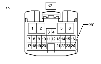
| *a | Front view of wire harness connector
(to 4WD ECU Assembly) |
Disconnect the 4WD ECU assembly connector.
Turn the engine switch on (IG).
Measure the voltage according to the value(s) in the table below.
- Standard Voltage:
Tester Connection Switch Condition Specified Condition N3-24 (IG1) - Body ground Engine switch on (IG) 11 to 14 V
- Result:
Proceed to OK NG
OK
NG
Turn the engine switch off.
Disconnect the N3 4WD ECU assembly connector.
Measure the resistance according to the value(s) in the table below.
- Standard Resistance:
Tester Connection Condition Specified Condition N3-1 (GND) - Body ground Always Below 1 Ω
- Result:
Proceed to OK NG
OK
NG
Turn the engine switch off.
Connect the GTS the DLC3.
Turn the engine switch on (IG).
Turn the GTS on.
Enter the following menus: Chassis / Four Wheel Drive / Data List.
According to the display on the GTS, read the Data List.
- Chassis > Four Wheel Drive > Data List
-
Tester Display Measurement Item Range Normal Condition Diagnostic Note 4WD Warning Light AWD warning (multi-information display) OFF / ON OFF: Warning off
ON: Warning on-
- Chassis > Four Wheel Drive > Data List
-
Tester Display 4WD Warning Light - 50003 448 114
Check the GTS display condition of the 4WD warning light.
- Result:
Result Proceed to Display of the Data List remains OFF A Display of the Data List remains ON B
A
for SFTM Made: Click hereVehicle Interior>METER / GAUGE / DISPLAY>METER / GAUGE SYSTEM (for SFTM Made)>HOW TO PROCEED WITH TROUBLESHOOTING202405,999999,_58,_083097,_0694858,RM100000002LUR9,
for GTMC Made: Click hereVehicle Interior>METER / GAUGE / DISPLAY>METER / GAUGE SYSTEM (for GTMC Made)>HOW TO PROCEED WITH TROUBLESHOOTING202405,999999,_58,_083097,_0694857,RM100000002LUOC,
B