RM36D0EC _51 Engine / Hybrid System _083048 HYBRID / BATTERY CONTROL _0709511 HYBRID CONTROL SYSTEM J

HYBRID / BATTERY CONTROL  HYBRID CONTROL SYSTEM  Inverter Low-voltage Circuit  


DESCRIPTION

The cause of the malfunction may be the low-voltage circuit.

Check whether there is an open circuit in the inverter +B low-voltage power source system or a problem in the communication between the hybrid vehicle control ECU assembly and inverter.

Related Parts Check
Area Inspection
Inverter +B low-voltage power source system check Check for inverter overcurrent malfunction.
Communication malfunction between hybrid vehicle control ECU assembly and MG-ECU inside inverter with converter assembly Check for inverter overcurrent malfunction due to communication malfunction.
Check for short to ground in inverter +B low-voltage power source system -

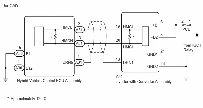
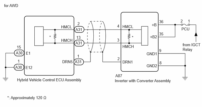
WIRING DIAGRAM

A556772E01
0.563,1.802 1.021,2 0.458,0.198 10 false A30 0.542,2.313 1,2.51 0.458,0.198 10 false A30 2.656,2.115 3.115,2.313 0.458,0.198 10 false A31 2.677,1.448 3.135,1.646 0.458,0.198 10 false A31 2.677,0.969 3.135,1.167 0.458,0.198 10 false A31 0.594,1.594 0.906,1.792 0.313,0.198 10 false 15 0.625,2.094 0.781,2.292 0.156,0.198 10 false 1 2.75,0.76 2.906,0.958 0.156,0.198 10 false 2 2.708,1.25 3.021,1.448 0.313,0.198 10 false 13 2.74,1.917 2.896,2.115 0.156,0.198 10 false 1 0.917,1.813 1.229,2.01 0.313,0.198 10 false E1 0.906,2.323 1.365,2.521 0.458,0.198 10 false E12 2.167,0.875 2.781,1.073 0.615,0.198 10 false HMCL 2.167,1.354 2.781,1.552 0.615,0.198 10 false HMCH 2.208,2.115 2.823,2.313 0.615,0.198 10 false DRN5 0.26,3.396 2.281,3.667 2.021,0.271 10 false *: Approximately 120 Ω 0.135,0.125 1.396,0.396 1.26,0.271 10 false for 2WD 0.604,2.76 3.552,3.073 2.948,0.313 10 false Hybrid Vehicle Control ECU Assembly 4.094,2.615 5.927,2.813 1.833,0.198 10 false A51 4.073,2.792 6.635,3.177 2.563,0.385 10 false Inverter with Converter Assembly 4.344,0.865 4.958,1.063 0.615,0.198 10 false HMCL 4.344,1.573 4.958,1.771 0.615,0.198 10 false HMCH 1.781,1.25 2.094,1.448 0.313,0.198 10 false * 4.688,1.24 5,1.438 0.313,0.198 10 false * 4.344,2.125 4.958,2.323 0.615,0.198 10 false DRN1 5.385,0.802 5.698,1 0.313,0.198 10 false +B 5.323,1.229 5.781,1.427 0.458,0.198 10 false +B2 5.198,1.833 5.813,2.031 0.615,0.198 10 false GND1 5.198,2.26 5.813,2.458 0.615,0.198 10 false GND2 6.438,0.948 6.896,1.146 0.458,0.198 10 false PCU 6.479,1.51 7.156,1.875 0.677,0.365 10 false from IGCT Relay 6.406,0.667 6.563,0.865 0.156,0.198 10 false 2 6.667,0.667 6.823,0.865 0.156,0.198 10 false 1 4.083,0.844 5.458,1.042 1.375,0.198 10 false 19 4.094,1.333 4.458,1.677 0.365,0.344 10 false 20 4.083,2.01 5.458,2.208 1.375,0.198 10 false 13 5.667,0.688 7.042,0.885 1.375,0.198 10 false 6 5.667,1.135 7.042,1.333 1.375,0.198 10 false 5 5.667,1.719 7.042,1.917 1.375,0.198 10 false 24 5.667,2.156 7.042,2.354 1.375,0.198 10 false 23

A556772E07
0.563,1.802 1.021,2 0.458,0.198 10 false A30 0.542,2.313 1,2.51 0.458,0.198 10 false A30 2.656,2.115 3.115,2.313 0.458,0.198 10 false A31 2.677,1.448 3.135,1.646 0.458,0.198 10 false A31 2.677,0.969 3.135,1.167 0.458,0.198 10 false A31 0.594,1.594 0.906,1.792 0.313,0.198 10 false 15 0.625,2.094 0.781,2.292 0.156,0.198 10 false 1 2.75,0.76 2.906,0.958 0.156,0.198 10 false 2 2.708,1.25 3.021,1.448 0.313,0.198 10 false 13 2.74,1.917 2.896,2.115 0.156,0.198 10 false 1 0.917,1.813 1.229,2.01 0.313,0.198 10 false E1 0.906,2.323 1.365,2.521 0.458,0.198 10 false E12 2.167,0.875 2.781,1.073 0.615,0.198 10 false HMCL 2.167,1.354 2.781,1.552 0.615,0.198 10 false HMCH 2.208,2.115 2.823,2.313 0.615,0.198 10 false DRN5 0.26,3.396 2.281,3.667 2.021,0.271 10 false *: Approximately 120 Ω 0.146,0.115 1.51,0.365 1.365,0.25 10 false for AWD 0.604,2.76 3.552,3.073 2.948,0.313 10 false Hybrid Vehicle Control ECU Assembly 4.094,2.615 5.927,2.813 1.833,0.198 10 false A87 4.073,2.792 6.635,3.177 2.563,0.385 10 false Inverter with Converter Assembly 4.344,0.865 4.958,1.063 0.615,0.198 10 false HMCL 4.344,1.573 4.958,1.771 0.615,0.198 10 false HMCH 1.75,1.24 2.063,1.438 0.313,0.198 10 false * 4.677,1.25 4.99,1.448 0.313,0.198 10 false * 4.344,2.125 4.958,2.323 0.615,0.198 10 false DRN1 5.385,0.802 5.698,1 0.313,0.198 10 false +B 5.323,1.229 5.781,1.427 0.458,0.198 10 false +B2 5.198,1.833 5.813,2.031 0.615,0.198 10 false GND1 5.198,2.26 5.813,2.458 0.615,0.198 10 false GND2 6.438,0.948 6.896,1.146 0.458,0.198 10 false PCU 6.479,1.51 7.156,1.875 0.677,0.365 10 false from IGCT Relay 6.406,0.667 6.563,0.865 0.156,0.198 10 false 2 6.667,0.667 6.823,0.865 0.156,0.198 10 false 1 4.156,0.844 5.531,1.042 1.375,0.198 10 false 4 4.156,1.344 4.521,1.688 0.365,0.344 10 false 3 4.167,2.01 5.542,2.208 1.375,0.198 10 false 2 5.646,0.688 7.021,0.885 1.375,0.198 10 false 36 5.646,1.125 7.021,1.323 1.375,0.198 10 false 35 5.646,1.719 7.021,1.917 1.375,0.198 10 false 9 5.656,2.156 7.031,2.354 1.375,0.198 10 false 8

CAUTION / NOTICE / HINT

This diagnostic procedure is referenced to in the diagnostic procedure of several DTCs.

If the result of this diagnostic procedure is normal, proceed as directed in the procedure for the DTC.

CAUTION:

Refer to the precautions before inspecting high voltage circuit.

Click hereEngine / Hybrid System>HYBRID / BATTERY CONTROL>HYBRID CONTROL SYSTEM>PRECAUTION


PROCEDURE

1.CHECK FUSE (PCU)
a.
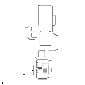
C408098C01
1.052,2.958 1.521,2.75 true 0.167,0.135 0.479,0.333 0.313,0.198 10 false *1 0.865,2.906 1.177,3.104 0.313,0.198 10 false *2
*1 No. 3 Relay Block and Junction Block Assembly
*2 PCU Fuse


Remove the PCU fuse from the No. 3 relay block and junction block assembly.


b.

Measure the resistance according to the value(s) in the table below.

Standard Resistance:
Tester Connection Condition Specified Condition
PCU fuse Always Below 1 Ω


c.

Install the PCU fuse.


Result:
Proceed to
OK
NG


OK

2.CHECK HARNESS AND CONNECTOR (INVERTER WITH CONVERTER ASSEMBLY POWER SOURCE CIRCUIT)

NG

5.CHECK HARNESS AND CONNECTOR (INVERTER WITH CONVERTER ASSEMBLY - PCU FUSE)
2.CHECK HARNESS AND CONNECTOR (INVERTER WITH CONVERTER ASSEMBLY POWER SOURCE CIRCUIT)
CAUTION:

Be sure to wear insulated gloves.


a.

Check that the service plug grip is not installed.

NOTICE:

After removing the service plug grip, do not turn the power switch on (READY), unless instructed by the repair manual because this may cause a malfunction.


b.

Disconnect the A51*1 or A87*2 inverter with converter assembly connector.

*1: for 2WD

*2: for AWD


c.
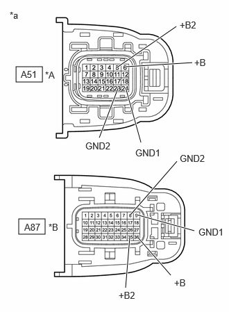
A556792C04
0.24,1 0.635,1.229 0.396,0.229 0.281,3.281 0.677,3.51 0.396,0.229 1.74,1.021 2.646,0.396 true 1.885,1 2.885,0.938 true 1.771,1.323 1.49,2.063 true 1.885,1.313 2.115,2.135 true 2.917,3.458 2.052,3.219 true 2.656,2.417 1.958,3.219 true 2.563,4.125 2.073,3.563 true 1.885,4.313 1.948,3.552 true 0.365,3.323 0.823,3.521 0.458,0.198 10 false A87 0.313,1.031 0.771,1.229 0.458,0.198 10 false A51 2.979,3.396 3.427,3.583 0.448,0.188 10 false GND1 2.031,2.208 2.615,2.406 0.583,0.198 10 false GND1 1.281,2.104 1.865,2.302 0.583,0.198 10 false GND2 2.698,2.292 3.281,2.49 0.583,0.198 10 false GND2 2.698,0.292 3.01,0.49 0.313,0.198 10 false +B2 2.917,0.854 3.229,1.052 0.313,0.198 10 false +B 2.615,4.156 2.927,4.354 0.313,0.198 10 false +B 1.781,4.344 2.094,4.542 0.313,0.198 10 false +B2 0.677,1.042 1.135,1.24 0.458,0.198 10 false *A 0.729,3.323 1.188,3.521 0.458,0.198 10 false *B 0.146,0.146 0.458,0.344 0.313,0.198 10 false *a
*A for 2WD
*B for AWD
*a Front view of wire harness connector
(to Inverter with Converter Assembly)


Measure the resistance according to the value(s) in the table below.
Standard Resistance:
for 2WD:
Tester Connection Condition Specified Condition
A51-24 (GND1) - Body ground Power switch off Below 1 Ω
A51-23 (GND2) - Body ground Power switch off Below 1 Ω

for AWD:
Tester Connection Condition Specified Condition
A87-9 (GND1) - Body ground Power switch off Below 1 Ω
A87-8 (GND2) - Body ground Power switch off Below 1 Ω


d.

Connect the cable to the negative (-) auxiliary battery terminal.


e.

Turn the power switch on (IG).


f.

Measure the voltage according to the value(s) in the table below.
Standard Voltage:
for 2WD:
Tester Connection Condition Specified Condition
A51-6 (+B) - Body ground Power switch on (IG) Same as auxiliary battery voltage
A51-5 (+B2) - Body ground Power switch on (IG) Same as auxiliary battery voltage

for AWD:
Tester Connection Condition Specified Condition
A87-36 (+B) - Body ground Power switch on (IG) Same as auxiliary battery voltage
A87-35 (+B2) - Body ground Power switch on (IG) Same as auxiliary battery voltage


NOTICE:

Turning the power switch on (IG) with the inverter with converter assembly connector disconnected causes other DTCs to be stored. Clear the DTCs after performing this inspection.


g.

Turn the power switch off.


h.

Disconnect the cable from the negative (-) auxiliary battery terminal and wait for 2 minutes or more.


i.

Reconnect the A51*1 or A87*2 inverter with converter assembly connector.

*1: for 2WD

*2: for AWD


Result:
Proceed to
OK
NG


OK

3.CHECK HARNESS AND CONNECTOR (HYBRID VEHICLE CONTROL ECU ASSEMBLY - INVERTER WITH CONVERTER ASSEMBLY)

NG

REPAIR OR REPLACE POWER SOURCE CIRCUIT

3.CHECK HARNESS AND CONNECTOR (HYBRID VEHICLE CONTROL ECU ASSEMBLY - INVERTER WITH CONVERTER ASSEMBLY)
CAUTION:

Be sure to wear insulated gloves.


a.

Check that the service plug grip is not installed.

NOTICE:

After removing the service plug grip, do not turn the power switch on (READY), unless instructed by the repair manual because this may cause a malfunction.


b.

Disconnect the A51*1 or A87*2 inverter with converter assembly connector.

*1: for 2WD

*2: for AWD


c.

Disconnect the A31 hybrid vehicle control ECU assembly connector.


d.

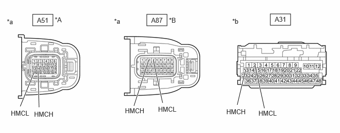
Measure the resistance according to the value(s) in the table below.

A556781C04
5.698,0.292 6.125,0.531 0.427,0.24 3.094,0.302 3.521,0.542 0.427,0.24 0.688,0.302 1.115,0.542 0.427,0.24 0.427,2.24 0.719,1.521 true 0.823,2.26 0.802,1.51 true 3.427,2.167 3.229,1.26 true 2.823,2.229 3.135,1.26 true 5,2.208 5.177,1.469 true 5.573,2.281 5.375,1.375 true 5.792,0.323 6.25,0.521 0.458,0.198 10 false A31 0.781,0.344 1.24,0.542 0.458,0.198 10 false A51 3.188,0.344 3.646,0.542 0.458,0.198 10 false A87 4.896,0.365 5.354,0.563 0.458,0.198 10 false *b 2.406,0.365 2.865,0.563 0.458,0.198 10 false *a 0.146,0.375 0.604,0.573 0.458,0.198 10 false *a 1.156,0.333 1.615,0.531 0.458,0.198 10 false *A 3.563,0.344 4.021,0.542 0.458,0.198 10 false *B 0.229,2.302 0.844,2.5 0.615,0.198 10 false HMCL 5.448,2.302 6.063,2.5 0.615,0.198 10 false HMCL 4.771,2.271 5.385,2.469 0.615,0.198 10 false HMCH 0.719,2.323 1.333,2.521 0.615,0.198 10 false HMCH 3.333,2.219 3.948,2.417 0.615,0.198 10 false HMCL 2.635,2.25 3.25,2.448 0.615,0.198 10 false HMCH
*A for 2WD *B for AWD
*a Front view of wire harness connector
(to Inverter with Converter Assembly)
*b Front view of wire harness connector
(to Hybrid Vehicle Control ECU Assembly)


Standard Resistance (Check for Open):
for 2WD:
Tester Connection Condition Specified Condition
A51-20 (HMCH) - A31-13 (HMCH) Power switch off Below 1 Ω
A51-19 (HMCL) - A31-2 (HMCL) Power switch off Below 1 Ω

for AWD:
Tester Connection Condition Specified Condition
A87-3 (HMCH) - A31-13 (HMCH) Power switch off Below 1 Ω
A87-4 (HMCL) - A31-2 (HMCL) Power switch off Below 1 Ω


Standard Resistance (Check for Short):
for 2WD:
Tester Connection Condition Specified Condition
A51-20 (HMCH) or A31-13 (HMCH) - Body ground and other terminals Power switch off 10 kΩ or higher
A51-19 (HMCL) or A31-2 (HMCL) - Body ground and other terminals Power switch off 10 kΩ or higher

for AWD:
Tester Connection Condition Specified Condition
A87-3 (HMCH) or A31-13 (HMCH) - Body ground and other terminals Power switch off 10 kΩ or higher
A87-4 (HMCL) or A31-2 (HMCL) - Body ground and other terminals Power switch off 10 kΩ or higher


e.

Connect the cable to the negative (-) auxiliary battery terminal.


f.

Turn the power switch on (IG).


g.

Measure the voltage according to the value(s) in the table below.

Standard Voltage:
for 2WD:
Tester Connection Condition Specified Condition
A51-20 (HMCH) or A31-13 (HMCH) - Body ground and other terminals Power switch on (IG) Below 1 V
A51-19 (HMCL) or A31-2 (HMCL) - Body ground and other terminals power switch on (IG) Below 1 V

for AWD:
Tester Connection Condition Specified Condition
A87-3 (HMCH) or A31-13 (HMCH) - Body ground and other terminals Power switch on (IG) Below 1 V
A87-4 (HMCL) or A31-2 (HMCL) - Body ground and other terminals power switch on (IG) Below 1 V


NOTICE:

Turning the power switch on (IG) with the hybrid vehicle control ECU assembly and inverter with converter assembly connectors disconnected causes other DTCs to be stored. Clear the DTCs after performing this inspection.


h.

Turn the power switch off.


i.

Disconnect the cable from the negative (-) auxiliary battery terminal and wait for 2 minutes or more.


j.

Reconnect the A31 hybrid vehicle control ECU assembly connector.


k.

Reconnect the A51*1 or A87*2 inverter with converter assembly connector.

*1: for 2WD

*2: for AWD


Result:
Proceed to
OK
NG


OK

4.CHECK HYBRID VEHICLE CONTROL ECU ASSEMBLY

NG

REPAIR OR REPLACE HARNESS OR CONNECTOR

4.CHECK HYBRID VEHICLE CONTROL ECU ASSEMBLY
a.

Disconnect the A31 hybrid vehicle control ECU assembly connector.


b.

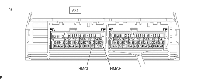
Measure the resistance according to the value(s) in the table below.

A460286C46
2.469,0.24 2.875,0.479 0.406,0.24 3.083,2.333 3.365,1.281 true 3.906,2.323 3.563,1.385 true 0.313,0.24 0.625,0.396 0.313,0.156 10 false *a 2.781,2.354 3.417,2.604 0.635,0.25 10 false HMCL 3.906,2.354 4.542,2.604 0.635,0.25 10 false HMCH 2.552,0.292 2.906,0.479 0.354,0.188 10 false A31
*a Component without harness connected
(Hybrid Vehicle Control ECU Assembly)
- -


Standard Resistance:
Tester Connection Condition Specified Condition
A31-2 (HMCL) - A31-13 (HMCH) Power switch off 80 to 170 Ω


c.

Reconnect the A31 hybrid vehicle control ECU assembly connector.


Result:
Proceed to
OK
NG


OK

INVERTER LOW-VOLTAGE CIRCUIT NORMAL (PERFORM NEXT STEP FOR REFERENCED DTC)

NG

5.CHECK HARNESS AND CONNECTOR (INVERTER WITH CONVERTER ASSEMBLY - PCU FUSE)
CAUTION:

Be sure to wear insulated gloves.


a.

Check that the service plug grip is not installed.

NOTICE:

After removing the service plug grip, do not turn the power switch on (READY), unless instructed by the repair manual because this may cause a malfunction.


b.

Disconnect the A51*1 or A87*2 inverter with converter assembly connector.

*1: for 2WD

*2: for AWD


c.
A556792C02
0.219,1 0.615,1.229 0.396,0.229 0.271,3.292 0.667,3.521 0.396,0.229 1.74,1.021 2.646,0.396 true 1.885,1 2.885,0.938 true 1.771,1.323 1.49,2.063 true 2.563,4.125 2.073,3.563 true 1.885,4.313 1.948,3.552 true 0.344,3.323 0.802,3.521 0.458,0.198 10 false A87 0.302,1.031 0.76,1.229 0.458,0.198 10 false A51 2.698,0.292 3.01,0.49 0.313,0.198 10 false +B2 2.917,0.854 3.229,1.052 0.313,0.198 10 false +B 2.615,4.156 2.927,4.354 0.313,0.198 10 false +B 1.781,4.344 2.094,4.542 0.313,0.198 10 false +B2 0.052,0.063 0.365,0.26 0.313,0.198 10 false *a 0.729,3.323 1.042,3.521 0.313,0.198 10 false *B 0.677,1.042 0.99,1.24 0.313,0.198 10 false *A
*A for 2WD
*B for AWD
*a Front view of wire harness connector
(to Inverter with Converter Assembly)


Measure the resistance according to the value(s) in the table below.

Standard Resistance:
for 2WD:
Tester Connection Condition Specified Condition
A51-6 (+B) - Body ground Power switch off 10 kΩ or higher
A51-5 (+B2) - Body ground Power switch off 10 kΩ or higher

for AWD:
Tester Connection Condition Specified Condition
A87-36 (+B) - Body ground Power switch off 10 kΩ or higher
A87-35 (+B2) - Body ground Power switch off 10 kΩ or higher


d.

Reconnect the A51*1 or A87*2 inverter with converter assembly connector.

*1: for 2WD

*2: for AWD


Result:
Proceed to
OK
NG


OK

6.REPLACE INVERTER WITH CONVERTER ASSEMBLY

NG

7.REPAIR OR REPLACE HARNESS OR CONNECTOR
Result:
Proceed to
NEXT


NEXT

REPLACE FUSE (PCU)