HYBRID / BATTERY CONTROL HYBRID CONTROL SYSTEM Shut Down Signal Circuit
DESCRIPTION
The cause of the malfunction may be a shutdown signal.
Check whether there is a shutdown signal +B short circuit.
| Area | Inspection |
|---|---|
| HSDN terminal | Check that the HSDN terminal voltage decreases to check for an open or short circuit while READY off (IG ON). |
| Hybrid vehicle control ECU assembly, inverter, wire harness | Check for open or short circuit in hybrid vehicle control ECU assembly, inverter and wire harness. |
SYSTEM DESCRIPTION
Power supply to the motor is cut off due to a shutdown signal sent from the hybrid vehicle control ECU assembly to the motor generator control ECU (MG ECU).
WIRING DIAGRAM
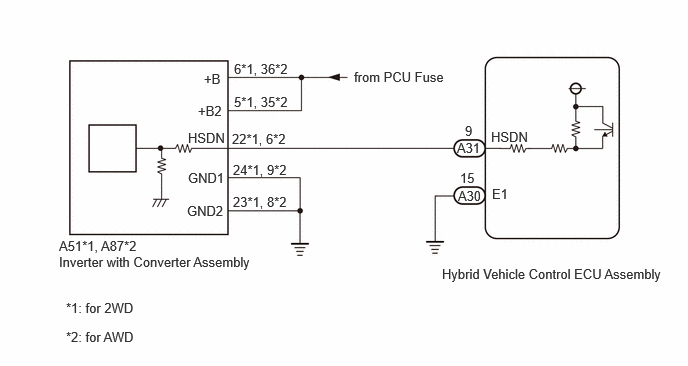
Refer to the wiring diagram for the ECU power source circuit.
CAUTION / NOTICE / HINT
This diagnostic procedure is referenced to in the diagnostic procedure of several DTCs.
If the result of this diagnostic procedure is normal, proceed as directed in the procedure for the DTC.
- CAUTION:
-
Refer to the precautions before inspecting high voltage circuit.
PROCEDURE
Turn the power switch on (IG).
Measure the voltage according to the value(s) in the table below.
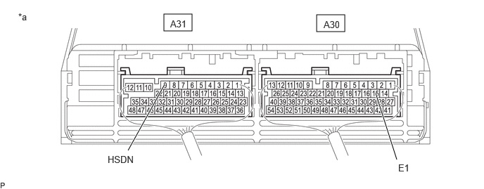
| *a | Component with harness connected
(Hybrid Vehicle Control ECU Assembly) |
- | - |
- Standard Voltage:
Tester Connection Condition Specified Condition A31-9 (HSDN) - A30-15 (E1) Power switch on (IG) Below 4.5 V
Turn the power switch off.
- Result:
Proceed to OK NG
OK
NG
Check vehicle condition.
- Result:
Result Proceed to for 2WD A for AWD B
A
B
- CAUTION:
-
Be sure to wear insulated gloves.
Check that the service plug grip is not installed.
- NOTICE:
-
After removing the service plug grip, do not turn the power switch on (READY), unless instructed by the repair manual because this may cause a malfunction.
Disconnect the A51 inverter with converter assembly connector.
Disconnect the A31 and A30 hybrid vehicle control ECU assembly connector.
Connect the cable to the negative (-) auxiliary battery terminal.
Turn the power switch on (IG).
Measure the voltage according to the value(s) in the table below.
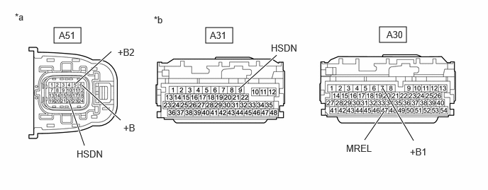
| *a | Front view of wire harness connector
(to Inverter with Converter Assembly) |
*b | Front view of wire harness connector
(to Hybrid Vehicle Control ECU Assembly) |
- Standard Voltage:
Tester Connection Condition Specified Condition A51-22 (HSDN) or A31-9 (HSDN) - Body ground Power switch on (IG) Below 1 V
- NOTICE:
-
Turning the power switch on (IG) with the hybrid vehicle control ECU assembly and inverter with converter assembly connector disconnected causes other DTCs to be stored. Clear the DTCs after performing this inspection.
Turn the power switch off.
Disconnect the cable from the negative (-) auxiliary battery terminal.
Measure the resistance according to the value(s) in the table below.
- Standard Resistance:
Tester Connection Condition Specified Condition A51-22 (HSDN) - A51-6 (+B) Power switch off 10 kΩ or higher A51-22 (HSDN) - A51-5 (+B2) Power switch off 10 kΩ or higher A31-9 (HSDN) - A30-7 (+B1) Power switch off 10 kΩ or higher A31-9 (HSDN) - A30-47 (MREL) Power switch off 10 kΩ or higher
Reconnect the A31 and A30 hybrid vehicle control ECU assembly connector.
Reconnect the A51 inverter with converter assembly connector.
- Result:
Proceed to OK NG
OK
NG
- CAUTION:
-
Be sure to wear insulated gloves.
Check that the service plug grip is not installed.
- NOTICE:
-
After removing the service plug grip, do not turn the power switch on (READY), unless instructed by the repair manual because this may cause a malfunction.
Disconnect the A51 inverter with converter assembly connector.
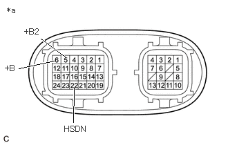
| *a | Component without harness connected
(Inverter with Converter Assembly) |
Measure the resistance according to the value(s) in the table below.
- Standard Resistance:
Tester Connection Condition Specified Condition 22 (HSDN) - 6 (+B) Power switch off 10 kΩ or higher 22 (HSDN) - 5 (+B2) Power switch off 10 kΩ or higher
Reconnect the A51 inverter with converter assembly connector.
- Result:
Proceed to OK NG
OK
NG
- CAUTION:
-
Be sure to wear insulated gloves.
Check that the service plug grip is not installed.
- NOTICE:
-
After removing the service plug grip, do not turn the power switch on (READY), unless instructed by the repair manual because this may cause a malfunction.
Disconnect the A87 inverter with converter assembly connector.
Disconnect the A31 and A30 hybrid vehicle control ECU assembly connector.
Connect the cable to the negative (-) auxiliary battery terminal.
Turn the power switch on (IG).
Measure the voltage according to the value(s) in the table below.
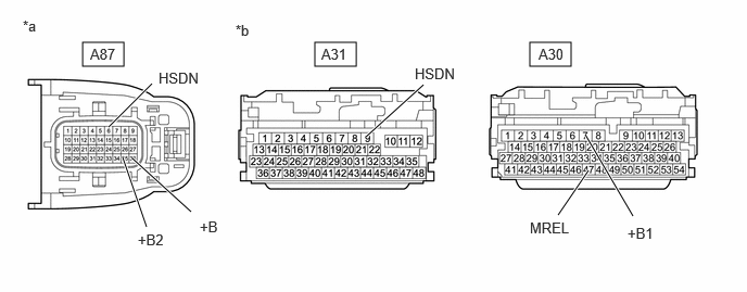
| *a | Front view of wire harness connector
(to Inverter with Converter Assembly) |
*b | Front view of wire harness connector
(to Hybrid Vehicle Control ECU Assembly) |
- Standard Voltage:
Tester Connection Condition Specified Condition A87-6 (HSDN) or A31-9 (HSDN) - Body ground Power switch on (IG) Below 1 V
- NOTICE:
-
Turning the power switch on (IG) with the hybrid vehicle control ECU assembly and inverter with converter assembly connector disconnected causes other DTCs to be stored. Clear the DTCs after performing this inspection.
Turn the power switch off.
Disconnect the cable from the negative (-) auxiliary battery terminal.
Measure the resistance according to the value(s) in the table below.
- Standard Resistance:
Tester Connection Condition Specified Condition A87-6 (HSDN) - A87-36 (+B) Power switch off 10 kΩ or higher A87-6 (HSDN) - A87-35 (+B2) Power switch off 10 kΩ or higher A31-9 (HSDN) - A30-7 (+B1) Power switch off 10 kΩ or higher A31-9 (HSDN) - A30-47 (MREL) Power switch off 10 kΩ or higher
Reconnect the A31 and A30 hybrid vehicle control ECU assembly connector.
Reconnect the A87 inverter with converter assembly connector.
- Result:
Proceed to OK NG
OK
NG
- CAUTION:
-
Be sure to wear insulated gloves.
Check that the service plug grip is not installed.
- NOTICE:
-
After removing the service plug grip, do not turn the power switch on (READY), unless instructed by the repair manual because this may cause a malfunction.
Disconnect the A87 inverter with converter assembly connector.
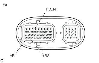
| *a | Component without harness connected
(Inverter with Converter Assembly) |
Measure the resistance according to the value(s) in the table below.
- Standard Resistance:
Tester Connection Condition Specified Condition 6 (HSDN) - 36 (+B) Power switch off 10 kΩ or higher 6 (HSDN) - 35 (+B2) Power switch off 10 kΩ or higher
Reconnect the A87 inverter with converter assembly connector.
- Result:
Proceed to OK NG
OK
NG