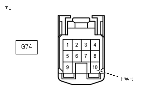
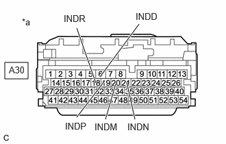
RM36D0EC _51 Engine / Hybrid System _083048 HYBRID / BATTERY CONTROL _0709511 HYBRID CONTROL SYSTEM J

HYBRID / BATTERY CONTROL  HYBRID CONTROL SYSTEM  Indicator Circuit  


DESCRIPTION

In accordance with the shift lever position, each shift position indicator light will turn on.

WIRING DIAGRAM
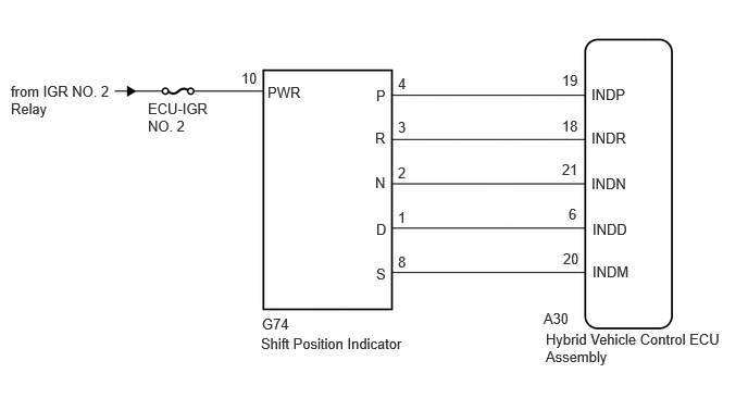
A550268E04
0.104,0.792 1.104,1.146 1,0.354 10 false from IGR NO. 2 Relay 1.417,0.958 2.031,1.344 0.615,0.385 10 false ECU-IGR NO. 2 2.313,0.667 2.583,0.896 0.271,0.229 10 false 10 2.563,0.802 3.021,1 0.458,0.198 10 false PWR 3.604,0.833 3.76,1.031 0.156,0.198 10 false P 3.594,1.24 3.75,1.438 0.156,0.198 10 false R 3.594,1.667 3.75,1.885 0.156,0.219 10 false N 3.604,2.115 3.76,2.333 0.156,0.219 10 false D 3.604,2.542 3.76,2.76 0.156,0.219 10 false S 3.813,0.719 3.969,0.917 0.156,0.198 10 false 4 3.813,1.135 3.969,1.333 0.156,0.198 10 false 3 3.813,1.573 3.969,1.771 0.156,0.198 10 false 2 3.813,2 3.969,2.198 0.156,0.198 10 false 1 3.813,2.427 3.969,2.625 0.156,0.198 10 false 8 5.667,0.823 6.281,1.021 0.615,0.198 10 false INDP 5.667,1.24 6.281,1.438 0.615,0.198 10 false INDR 5.667,1.677 6.281,1.875 0.615,0.198 10 false INDN 5.677,2.115 6.292,2.313 0.615,0.198 10 false INDD 5.677,2.521 6.292,2.719 0.615,0.198 10 false INDM 5.385,0.688 5.698,0.885 0.313,0.198 10 false 19 5.385,1.125 5.698,1.323 0.313,0.198 10 false 18 5.385,1.542 5.698,1.74 0.313,0.198 10 false 21 5.448,1.969 5.76,2.167 0.313,0.198 10 false 6 5.396,2.396 5.708,2.594 0.313,0.198 10 false 20 5.208,2.969 5.583,3.156 0.375,0.188 10 false A30 2.51,3.021 2.823,3.219 0.313,0.198 10 false G74 2.5,3.208 4.229,3.521 1.729,0.313 10 false Shift Position Indicator 5.229,3.167 6.927,3.51 1.698,0.344 10 false Hybrid Vehicle Control ECU Assembly

PROCEDURE

1.CHECK SHIFT POSITION INDICATOR
a.

Turn the power switch on (ACC).


b.

Check that each shift position indicator light turns on correctly.

Result:
Result Proceed to
All shift position indicator lights turn on simultaneously A
Shift position indicator lights other than corresponding one turns on B
Corresponding shift position indicator light does not turn on C
No shift position indicator lights turn on D


c.

Turn the power switch off.


A

2.CHECK HARNESS AND CONNECTOR (CHECK FOR SHORT TO GND)

B

2.CHECK HARNESS AND CONNECTOR (CHECK FOR SHORT TO GND)

C

4.CHECK HARNESS AND CONNECTOR (POWER SOURCE CIRCUIT)

D

4.CHECK HARNESS AND CONNECTOR (POWER SOURCE CIRCUIT)
2.CHECK HARNESS AND CONNECTOR (CHECK FOR SHORT TO GND)
a.

Disconnect the A30 hybrid vehicle control ECU assembly connector.
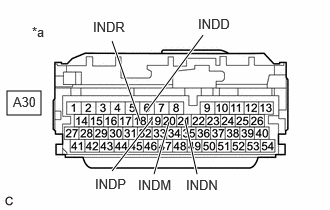

b.
A556736C40
0.073,0.948 0.427,1.198 0.354,0.25 1.167,0.427 1.458,1.26 true 1.167,1.781 1.583,1.24 true 2.052,1.813 1.927,1.25 true 2.115,0.365 1.521,1.167 true 1.604,1.813 1.76,1.271 true 0.333,0.25 0.646,0.448 0.313,0.198 10 false *a 0.969,0.198 1.385,0.385 0.417,0.188 10 false INDR 0.99,1.833 1.406,2.021 0.417,0.188 10 false INDP 0.135,0.979 0.438,1.156 0.302,0.177 10 false A30 2.063,0.167 2.479,0.354 0.417,0.188 10 false INDD 1.438,1.844 1.854,2.031 0.417,0.188 10 false INDM 1.938,1.844 2.354,2.031 0.417,0.188 10 false INDN
*a Front view of wire harness connector
(to Hybrid Vehicle Control ECU Assembly)


Measure the resistance according to the value(s) in the table below.

Standard Resistance:
Tester Connection Condition Specified Condition
A30-19 (INDP) - Body ground and other terminals Always 10 kΩ or higher
A30-18 (INDR) - Body ground and other terminals Always 10 kΩ or higher
A30-21 (INDN) - Body ground and other terminals Always 10 kΩ or higher
A30-6 (INDD) - Body ground and other terminals Always 10 kΩ or higher
A30-20 (INDM) - Body ground and other terminals Always 10 kΩ or higher


c.

Reconnect the A30 hybrid vehicle control ECU assembly connector.


Result:
Proceed to
OK
NG


OK

NG

3.CHECK HARNESS AND CONNECTOR (HYBRID VEHICLE CONTROL ECU ASSEMBLY - SHIFT POSITION INDICATOR)
a.

Disconnect the A30 hybrid vehicle control ECU assembly connector.


b.

Disconnect the G74 shift position indicator connector.
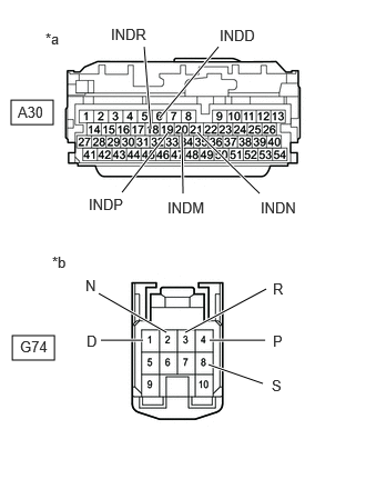

c.
C408038C19
0.104,0.938 0.5,1.167 0.396,0.229 0.115,3.146 0.51,3.375 0.396,0.229 1.969,3.188 2.49,3.188 true 1.74,3.115 2.5,2.708 true 1.563,3.115 0.927,2.75 true 1.344,3.188 0.948,3.188 true 1.958,3.417 2.469,3.594 true 1.417,1.208 1.354,0.438 true 1.5,1.104 2.052,0.438 true 1.146,1.802 1.573,1.25 true 1.719,1.813 1.708,1.24 true 2.438,1.813 1.854,1.24 true 0.49,2.375 0.802,2.573 0.313,0.198 10 false *b 0.167,0.969 0.479,1.167 0.313,0.198 10 false A30 0.188,3.167 0.5,3.365 0.313,0.198 10 false G74 0.802,2.594 1.115,2.792 0.313,0.198 10 false N 0.813,3.115 1.125,3.313 0.313,0.198 10 false D 2.563,2.625 2.875,2.823 0.313,0.198 10 false R 2.563,3.115 2.875,3.313 0.313,0.198 10 false P 2.552,3.531 2.865,3.729 0.313,0.198 10 false S 1.573,1.865 1.99,2.083 0.417,0.219 10 false INDM 2.063,0.25 2.479,0.469 0.417,0.219 10 false INDD 2.448,1.865 2.865,2.083 0.417,0.219 10 false INDN 0.833,1.833 1.25,2.052 0.417,0.219 10 false INDP 1.042,0.24 1.458,0.458 0.417,0.219 10 false INDR 0.427,0.281 0.74,0.479 0.313,0.198 10 false *a
*a Front view of wire harness connector
(to Hybrid Vehicle Control ECU Assembly)
*b Front view of wire harness connector
(to Shift Position Indicator)


Measure the resistance according to the value(s) in the table below.

Standard Resistance:
Tester Connection Condition Specified Condition
A30-19 (INDP) or G74-4 (P) - Body ground and other terminals Always 10 kΩ or higher
A30-18 (INDR) or G74-3 (R) - Body ground and other terminals Always 10 kΩ or higher
A30-21 (INDN) or G74-2 (N) - Body ground and other terminals Always 10 kΩ or higher
A30-6 (INDD) or G74-1 (D) - Body ground and other terminals Always 10 kΩ or higher
A30-20 (INDM) or G74-8 (S) - Body ground and other terminals Always 10 kΩ or higher


d.

Reconnect the G74 shift position indicator connector.


e.

Reconnect the A30 hybrid vehicle control ECU assembly connector.


Result:
Proceed to
OK
NG


OK

NG

REPAIR OR REPLACE HARNESS OR CONNECTOR

4.CHECK HARNESS AND CONNECTOR (POWER SOURCE CIRCUIT)
a.

Disconnect the G74 shift position indicator connector.


b.

Turn the power switch on (ACC).


c.
A406717C11
0.333,0.865 0.792,1.156 0.458,0.292 2.063,1.5 2.531,1.646 true 0.448,0.927 0.906,1.125 0.458,0.198 10 false G74 0.115,0.094 0.573,0.292 0.458,0.198 10 false *a 2.583,1.625 3.042,1.823 0.458,0.198 10 false PWR
*a Front view of wire harness connector
(to Shift Position Indicator)


Measure the voltage according to the value(s) in the table below.

Standard Voltage:
Tester Connection Condition Specified Condition
G74-10 (PWR) - Body ground Power switch on (ACC) 11 to 14 V


d.

Turn the power switch off.


e.

Reconnect the G74 shift position indicator connector.


Result:
Proceed to
OK
NG


OK

5.CHECK HARNESS AND CONNECTOR (CHECK FOR OPEN)

NG

REPAIR OR REPLACE POWER SOURCE CIRCUIT

5.CHECK HARNESS AND CONNECTOR (CHECK FOR OPEN)
a.

Disconnect the A30 hybrid vehicle control ECU assembly connector.


b.

Turn the power switch on (ACC).


c.
A556736C41
0.073,0.948 0.427,1.198 0.354,0.25 1.167,0.427 1.458,1.26 true 1.167,1.781 1.583,1.24 true 2.052,1.813 1.927,1.25 true 2.115,0.365 1.521,1.167 true 1.604,1.813 1.76,1.271 true 0.333,0.25 0.646,0.448 0.313,0.198 10 false *a 0.969,0.198 1.385,0.385 0.417,0.188 10 false INDR 0.99,1.833 1.406,2.021 0.417,0.188 10 false INDP 0.135,0.979 0.438,1.156 0.302,0.177 10 false A30 2.063,0.167 2.479,0.354 0.417,0.188 10 false INDD 1.438,1.844 1.854,2.031 0.417,0.188 10 false INDM 1.938,1.844 2.354,2.031 0.417,0.188 10 false INDN
*a Front view of wire harness connector
(to Hybrid Vehicle Control ECU Assembly)


Measure the voltage according to the value(s) in the table below.

Standard Voltage:
Tester Connection Condition Specified Condition
A30-19 (INDP) - Body ground and other terminals Power switch on (ACC) 11 to 14 V
A30-18 (INDR) - Body ground and other terminals Power switch on (ACC) 11 to 14 V
A30-21 (INDN) - Body ground and other terminals Power switch on (ACC) 11 to 14 V
A30-6 (INDD) - Body ground and other terminals Power switch on (ACC) 11 to 14 V
A30-20 (INDM) - Body ground and other terminals Power switch on (ACC) 11 to 14 V


d.

Turn the power switch off.


e.

Reconnect the A30 hybrid vehicle control ECU assembly connectors.


Result:
Proceed to
OK
NG


OK

NG

6.CHECK HARNESS AND CONNECTOR (HYBRID VEHICLE CONTROL ECU ASSEMBLY - SHIFT POSITION INDICATOR)
a.

Disconnect the A30 hybrid vehicle control ECU assembly connectors.


b.

Disconnect the G74 shift position indicator connector.


c.
C408038C20
0.104,0.938 0.5,1.167 0.396,0.229 0.115,3.146 0.51,3.375 0.396,0.229 1.969,3.188 2.49,3.188 true 1.74,3.115 2.5,2.708 true 1.563,3.115 0.927,2.75 true 1.344,3.188 0.948,3.188 true 1.958,3.417 2.469,3.594 true 1.417,1.208 1.354,0.438 true 1.5,1.104 2.052,0.438 true 1.146,1.802 1.573,1.25 true 1.719,1.813 1.708,1.24 true 2.438,1.813 1.854,1.24 true 0.49,2.375 0.802,2.573 0.313,0.198 10 false *b 0.167,0.969 0.479,1.167 0.313,0.198 10 false A30 0.188,3.167 0.5,3.365 0.313,0.198 10 false G74 0.802,2.594 1.115,2.792 0.313,0.198 10 false N 0.813,3.115 1.125,3.313 0.313,0.198 10 false D 2.563,2.625 2.875,2.823 0.313,0.198 10 false R 2.563,3.115 2.875,3.313 0.313,0.198 10 false P 2.552,3.531 2.865,3.729 0.313,0.198 10 false S 1.573,1.865 1.99,2.083 0.417,0.219 10 false INDM 2.063,0.25 2.479,0.469 0.417,0.219 10 false INDD 2.448,1.865 2.865,2.083 0.417,0.219 10 false INDN 0.833,1.833 1.25,2.052 0.417,0.219 10 false INDP 1.042,0.24 1.458,0.458 0.417,0.219 10 false INDR 0.427,0.281 0.74,0.479 0.313,0.198 10 false *a
*a Front view of wire harness connector
(to Hybrid Vehicle Control ECU Assembly)
*b Front view of wire harness connector
(to Shift Position Indicator)


Measure the resistance according to the value(s) in the table below.

Standard Resistance:
Tester Connection Condition Specified Condition
A30-19 (INDP) - G74-4 (P) Always Below 1 Ω
A30-18 (INDR) - G74-3 (R) Always Below 1 Ω
A30-21 (INDN) - G74-2 (N) Always Below 1 Ω
A30-6 (INDD) - G74-1 (D) Always Below 1 Ω
A30-20 (INDM) - G74-8 (S) Always Below 1 Ω


d.

Reconnect the G74 shift position indicator connector.


e.

Reconnect the A30 hybrid vehicle control ECU assembly connectors.


Result:
Proceed to
OK
NG


OK

NG

REPAIR OR REPLACE HARNESS OR CONNECTOR