HYBRID / BATTERY CONTROL HYBRID CONTROL SYSTEM TRAIL Switch Circuit
DESCRIPTION
The TRAIL mode signal will be sent to the hybrid vehicle control ECU assembly when the TRAIL mode switch (integration control and panel assembly) is operated. If the specified conditions are met, the system enters TRAIL mode and the vehicle will be driven using TRAIL mode. This signal is then transmitted from the hybrid vehicle control ECU assembly via CAN to the combination meter assembly to illuminate the TRAIL indicator.
WIRING DIAGRAM
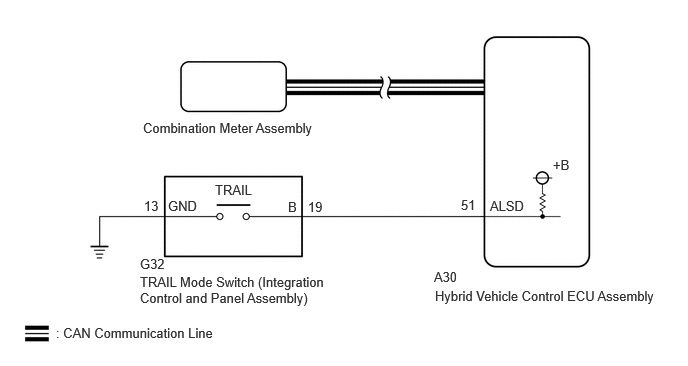
PROCEDURE
Connect the GTS to the DLC3.
Turn the power switch on (IG).
Turn the GTS on.
Enter the following menus: System Select / CAN Bus Check.
- CAN Bus Check
- 50007
- Result:
Result Proceed to All of the ECUs and sensors that are currently connected to the CAN communication system are displayed. A None of the ECUs and sensors that are currently connected to the CAN communication system are displayed, or some of them are not displayed. B
Turn the power switch off.
A
B
for GTMC Made: Click herePower Source / Network>NETWORKING>CAN COMMUNICATION SYSTEM (for GTMC Made HV Model)>HOW TO PROCEED WITH TROUBLESHOOTING202409,999999,_57,_083091,_0694855,RM100000002NTBR,
for SFTM Made: Click herePower Source / Network>NETWORKING>CAN COMMUNICATION SYSTEM (for SFTM Made HV Model)>HOW TO PROCEED WITH TROUBLESHOOTING202409,999999,_57,_083091,_0694853,RM100000002NT0M,
Connect the GTS to the DLC3.
Turn the power switch on (IG).
Turn the GTS on.
Enter the following menus: System Select / Health Check.
Check for DTCs.
- Result:
Result Proceed to No DTCs are output. A DTCs are output. B
Turn the power switch off.
A
B
Connect the GTS to the DLC3.
Turn the power switch on (IG).
Turn the GTS on.
Enter the following menus: Powertrain / Hybrid Control / Data List / AUTO LSD Switch.
- Powertrain > Hybrid Control > Data List
-
Tester Display Auto LSD Switch - 50003 397 646
Read the value displayed on the GTS.
- Powertrain > Hybrid Control > Data List
-
Tester Display Measurement Item Range Normal Condition Auto LSD Switch TRAIL switch (integration control and panel assembly) condition ON or OFF TRAIL mode switch (integration control and panel assembly) being pushed and held:
ON
TRAIL mode switch (integration control and panel assembly) not operated:
OFF
- Result:
Result Proceed to The tester display changes according to the TRAIL mode switch operation. A The tester display does not change according to the TRAIL mode switch operation. B
Turn the power switch off.
A
B
- Result:
Proceed to OK NG
OK
NG
Disconnect the G32 TRAIL mode switch (integration control and panel assembly) connector.
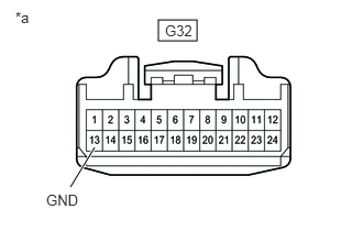
| *a | Front view of wire harness connector
(to TRAIL Mode Switch (Integration Control and Panel Assembly)) |
Measure the resistance according to the value(s) in the table below.
- Standard Resistance:
Tester Connection Condition Specified Condition G32-13 (GND) - Body ground Always Below 1 Ω
Reconnect the G32 TRAIL mode switch (integration control and panel assembly) connector.
- Result:
Proceed to OK NG
OK
NG
Disconnect the A30 hybrid vehicle control ECU assembly connector.
Disconnect the G32 TRAIL mode switch (integration control and panel assembly) connector.
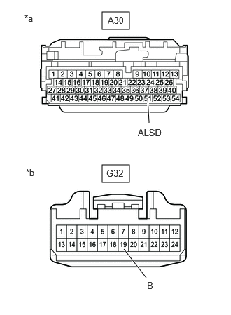
| *a | Front view of wire harness connector
(to Hybrid Vehicle Control ECU Assembly) |
| *b | Front view of wire harness connector
(to TRAIL Mode Switch (Integration Control and Panel Assembly)) |
Measure the resistance according to the value(s) in the table below.
- Standard Resistance:
Tester Connection Condition Specified Condition A30-51 (ALSD) - G32-19 (B) Always Below 1 Ω A30-51 (ALSD) or G32-19 (B) - Body ground Always 10 kΩ or higher
Reconnect the G32 TRAIL mode switch (integration control and panel assembly) connector.
Reconnect the A30 hybrid vehicle control ECU assembly connector.
- Result:
Proceed to OK NG
OK
NG