HYBRID / BATTERY CONTROL HYBRID CONTROL SYSTEM Transmission Control Switch Circuit
DESCRIPTION
When the shift lever is in S, different ranges can be chosen using the floor shift sequential gate.
WIRING DIAGRAM
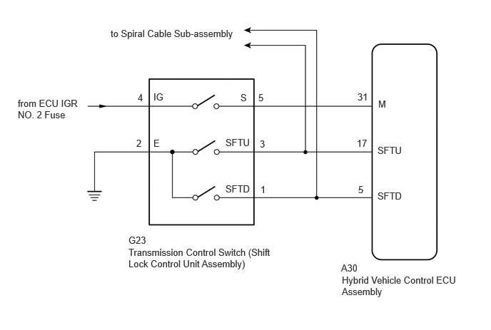
PROCEDURE
Connect the GTS to the DLC3.
Turn the power switch on (IG).
Enter the following menus: Powertrain / Hybrid Control / Data List / Sports Shift Position.
- Powertrain > Hybrid Control > Data List
-
Tester Display Sports Shift Position - 50003 397 233
Read the value displayed on the GTS.
- Powertrain > Hybrid Control > Data List
-
Tester Display Measurement Item Range Normal Condition Sports Shift Position Sports shift position 0 to 255 Shift lever in S, "+" or "-": 1 to 6
Shift lever in any position other than S, "+" and "-": 255
- Result:
Result Proceed to The tester display changes according to the shift lever operation. A The tester display does not change according to the shift lever operation. B
Turn the power switch off.
A
B
Connect the GTS to the DLC3.
Turn the power switch on (IG).
Enter the following menus: Powertrain / Hybrid Control / Data List / Sports Shift UP Signal, Sports Shift DOWN Signal.
- Powertrain > Hybrid Control > Data List
-
Tester Display Sports Shift UP Signal Sports Shift DOWN Signal - 50003 397 83,82
Read the value displayed on the GTS.
- Powertrain > Hybrid Control > Data List
-
Tester Display Measurement Item Range Normal Condition Sports Shift UP Signal Operation of "+" transmission control switch. ON or OFF Shift lever held in "+" operated: ON
Shift lever in S: OFFSports Shift DOWN Signal Operation of "-" transmission control switch. ON or OFF Shift lever held in "-" operated: ON
Shift lever in S: OFF
- Result:
Result Proceed to The tester display changes according to the transmission control switch (shift lock control unit assembly) operation. A The tester display does not change according to the transmission control switch (shift lock control unit assembly) operation. B
Turn the power switch off.
A
B
- Result:
Proceed to OK NG
OK
NG
Disconnect the G23 transmission control switch (shift lock control unit assembly) connector.
Turn the power switch on (IG).

| *a | Front view of wire harness connector
(to Transmission Control Switch (Shift Lock Control Unit Assembly)) |
Measure the voltage according to the value(s) in the table below.
- Standard Voltage:
Tester Connection Condition Specified Condition G23-4 (IG) - Body ground Power switch on (IG) 11 to 14 V
Turn the power switch off.
Measure the voltage according to the value(s) in the table below.
- Standard Voltage:
Tester Connection Condition Specified Condition G23-4 (IG) - Body ground Power switch off Below 1 V
Measure the resistance according to the value(s) in the table below.
- Standard Resistance:
Tester Connection Condition Specified Condition G23-2 (E) - Body ground Power switch off Below 1 Ω
Reconnect the G23 transmission control switch (shift lock control unit assembly) connector.
- Result:
Proceed to OK NG
OK
NG
Disconnect the G23 transmission control switch (shift lock control unit assembly) connector.
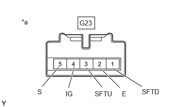
| *a | Component without harness connected
(Transmission Control Switch (Shift Lock Control Unit Assembly)) |
Measure the resistance according to the value(s) in the table below when the shift lever is moved to each position.
- Standard Resistance:
Tester Connection Condition Specified Condition G23-4 (IG) - G23-5 (S) Shift lever in S
Shift lever held in "+" or "-"Below 1 Ω G23-4 (IG) - G23-5 (S) Shift lever in any position except S 10 kΩ or higher G23-3 (SFTU) - G23-2 (E) Shift lever held in "+" Below 1 Ω G23-3 (SFTU) - G23-2 (E) Shift lever in S 10 kΩ or higher G23-1 (SFTD) - G23-2 (E) Shift lever held in "-" Below 1 Ω G23-1 (SFTD) - G23-2 (E) Shift lever in S 10 kΩ or higher
Reconnect the G23 transmission control switch (shift lock control unit assembly) connector.
- Result:
Proceed to OK NG
OK
NG
Disconnect the A30 hybrid vehicle control ECU assembly connector.
Disconnect the G20 spiral cable sub-assembly connector.
Turn the power switch on (IG).
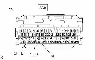
| *a | Front view of wire harness connector
(to Hybrid Vehicle Control ECU Assembly) |
Measure the voltage according to the value(s) in the table below when the shift lever is moved to each position.
- Standard Voltage:
Tester Connection Condition Specified Condition A30-31 (M) - Body ground Power switch on (IG)
Shift lever in S, "+" or "-"11 to 14 V Power switch on (IG)
Except shift lever in S, "+" and "-"Below 1 V
- NOTICE:
-
If the power switch is turned on (IG) with the hybrid vehicle control ECU assembly connector disconnected, other DTCs will be stored. After performing the inspection, clear the DTCs.
Turn the power switch off.
Measure the resistance according to the value(s) in the table below when the shift lever is moved to each position.
- Standard Resistance:
Tester Connection Condition Specified Condition A30-17 (SFTU) - Body ground Shift lever held in "+" Below 1 Ω A30-17 (SFTU) - Body ground Shift lever in S 10 kΩ or higher A30-5 (SFTD) - Body ground Shift lever held in "-" Below 1 Ω A30-5 (SFTD) - Body ground Shift lever in S 10 kΩ or higher
Reconnect the G20 spiral cable sub-assembly connector.
Reconnect the A30 hybrid vehicle control ECU assembly connector.
- Result:
Proceed to OK NG
OK
NG
Disconnect the G23 transmission control switch (shift lock control unit assembly) connector.
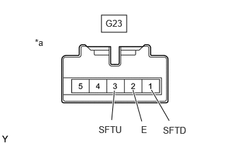
| *a | Component without harness connected
(Transmission Control Switch (Shift Lock Control Unit Assembly)) |
Measure the resistance according to the value(s) in the table below when the shift lever is moved to each position.
- Standard Resistance:
Tester Connection Condition Specified Condition G23-3 (SFTU) - G23-2 (E) Shift lever held in "+" Below 1 Ω G23-3 (SFTU) - G23-2 (E) Shift lever in S 10 kΩ or higher G23-1 (SFTD) - G23-2 (E) Shift lever held in "-" Below 1 Ω G23-1 (SFTD) - G23-2 (E) Shift lever in S 10 kΩ or higher
Reconnect the G23 transmission control switch (shift lock control unit assembly) connector.
- Result:
Proceed to OK NG
OK
NG
Disconnect the A30 hybrid vehicle control ECU assembly connector.
Disconnect the G20 spiral cable sub-assembly connector.
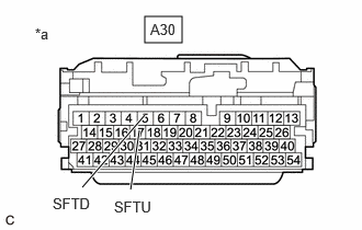
| *a | Front view of wire harness connector
(to Hybrid Vehicle Control ECU Assembly) |
Measure the resistance according to the value(s) in the table below when the shift lever is moved to each position.
- Standard Resistance:
Tester Connection Condition Specified Condition A30-17 (SFTU) - Body ground Shift lever held in "+" Below 1 Ω Shift lever in S 10 kΩ or higher A30-5 (SFTD) - Body ground Shift lever held in "-" Below 1 Ω Shift lever in S 10 kΩ or higher
Reconnect the G20 spiral cable sub-assembly connector.
Reconnect the A30 hybrid vehicle control ECU assembly connector.
- Result:
Proceed to OK NG
OK
NG