HYBRID / BATTERY CONTROL HYBRID CONTROL SYSTEM Brake Override System
DESCRIPTION
When the vehicle is being driven with the accelerator pedal depressed, depressing the brake pedal without releasing the accelerator pedal will activate the brake override system to restrict hybrid system output. The conditions for activating the brake override system as well as the items that are controlled are explained below.
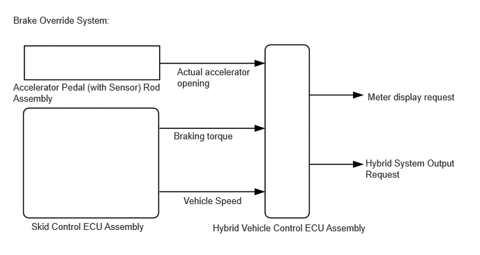
- Activation Conditions:
- ·
The accelerator pedal and brake pedal are depressed at the same time.
- NOTICE:
-
Brake override control may not be performed depending on the relationship between accelerator opening and vehicle speed.
- Items Controlled:
- ·
Controls hybrid system output
- HINT:
- ·
When the control is operating, hybrid system output is controlled in accordance with the brake pedal stroke.
·When the hybrid system output is reduced to a specified level because the accelerator pedal and brake pedal are depressed at the same time, an indicator is displayed on the meter. (Operation of the system can be confirmed when the indicator is displayed on the meter.)
- Deactivation Conditions:
- ·
The accelerator pedal or brake pedal is released.
CAUTION / NOTICE / HINT
- Inspection Method
-
Drive at 10 km/h (6 mph), depress the accelerator pedal by 1/2 to 3/4 and keep it in that position. Under these conditions, if hybrid system output is controlled when the brake pedal is depressed by the left foot of the driver, it can be confirmed that the brake override system has operated.
- CAUTION:
-
Perform this road test only in an appropriate safe location, in accordance with all local laws.
-
Pay careful attention to the surroundings when performing the road test.
- HINT:
-
The brake override system restricts hybrid system output if the brake pedal is depressed when driving with the accelerator pedal depressed. If a customer reports experiencing a loss of power (requested accelerator torque) after the accelerator and brake pedals have both been intentionally depressed, explain that this is not a malfunction, and depressing both the accelerator and brake pedals at the same time should be avoided.
PROCEDURE
Connect the GTS to the DLC3.
Turn the power switch on (IG).
Turn the GTS on.
Enter the following menus: System Select / Health Check.
Check for DTCs.
- Result:
Result Proceed to No DTCs are output. A DTCs are output. B
Turn the power switch off.
A
B
Connect the GTS to the DLC3.
Turn the power switch on (READY).
Turn the GTS on.
Enter the following menus: Powertrain / Hybrid Control / Data List / Master Cylinder Control Torque.
- Powertrain > Hybrid Control > Data List
-
Tester Display Master Cylinder Control Torque - 50003 397 89
Read the value displayed on the GTS.
- Result:
Result Proceed to Display changes according to brake pedal depression force A Other than above B
Turn the power switch off.
A
B
Connect the GTS to the DLC3.
Turn the power switch on (IG).
Turn the GTS on.
Enter the following menus: Powertrain / Hybrid Control / Data List / Accelerator Position Sensor No. 1 Voltage %, Accelerator Position Sensor No. 2 Voltage %.
- Powertrain > Hybrid Control > Data List
-
Tester Display Accelerator Position Sensor No.1 Voltage % Accelerator Position Sensor No.2 Voltage % - 50003 397 23,24
Read the values displayed on the GTS.
- Standard:
Inspection Condition Specified Condition Accelerator pedal fully released → fully depressed Value (%) changes with accelerator pedal operation
Turn the power switch off.
- Result:
Proceed to OK NG
OK
NG
Connect the GTS to the DLC3.
Turn the power switch on (READY).
Turn the GTS on.
Enter the following menus: Powertrain / Hybrid Control / Data List / Vehicle Speed.
- Powertrain > Hybrid Control > Data List
-
Tester Display Vehicle Speed - 50003 397 12
Read the value displayed on the GTS.
- Standard:
Inspection Condition Specified Condition Vehicle stopped 0 km/h (0 mph) Vehicle being driven at a constant speed
(16 to 64 km/h (10 to 40 mph))No large fluctuations in displayed speed
- CAUTION:
-
Perform this road test only in an appropriate safe location, in accordance with all local laws.
- HINT:
-
Data can be captured relatively easily by using the snapshot function in the Data List. Confirm the data after performing the drive test.
Turn the power switch off.
- Result:
Proceed to OK NG
OK
NG
for GTMC Made: Click hereVehicle Interior>METER / GAUGE / DISPLAY>METER / GAUGE SYSTEM (for GTMC Made)>Speed Signal Circuit202409,999999,_58,_083097,_0694857,RM100000002NUJH,
for SFTM Made: Click hereVehicle Interior>METER / GAUGE / DISPLAY>METER / GAUGE SYSTEM (for SFTM Made)>Speed Signal Circuit202409,999999,_58,_083097,_0694858,RM100000002NUK5,
Connect the GTS to the DLC3.
Turn the power switch on (READY).
Turn the GTS on.
Enter the following menus: Chassis / ABS/VSC/TRAC / Data List / All Data / FR Wheel Speed, FL Wheel Speed, RR Wheel Speed and RL Wheel Speed.
- Chassis > ABS/VSC/TRC > Data List
-
Tester Display FR Wheel Speed FL Wheel Speed RR Wheel Speed RL Wheel Speed - 50003 105 1,2,3,4
Read the values displayed on the GTS.
- Standard:
Inspection Condition Specified Condition Vehicle stopped 0 km/h (0 mph) Vehicle being driven at a constant speed
(16 to 64 km/h (10 to 40 mph))No large fluctuations in displayed speed
- CAUTION:
-
Perform this road test only in an appropriate safe location, in accordance with all local laws.
- HINT:
-
Data can be captured relatively easily by using the snapshot function in the Data List. Confirm the data after performing the drive test.
Turn the power switch off.
- Result:
Proceed to OK NG
OK
NG