HYBRID / BATTERY CONTROL HYBRID CONTROL SYSTEM P212012 Throttle/Pedal Position Sensor/Switch "D" Circuit Short to Auxiliary Battery P212014 Throttle/Pedal Position Sensor/Switch "D" Circuit Short to Ground or Open P21201C Throttle/Pedal Position Sensor/Switch "D" Voltage Out of Range P21201F Throttle/Pedal Position Sensor/Switch "D" Circuit Intermittent P212512 Throttle/Pedal Position Sensor/Switch "E" Circuit Short to Auxiliary Battery P212514 Throttle/Pedal Position Sensor/Switch "E" Circuit Short to Ground or Open P21251C Throttle/Pedal Position Sensor/Switch "E" Voltage Out of Range P21251F Throttle/Pedal Position Sensor/Switch "E" Circuit Intermittent P213800 Throttle/Pedal Position Sensor/Switch "D"/" E" Voltage Correlation P21382B Throttle/Pedal Position Sensor/Switch "D"/"E" Signal Cross Coupled
DTC SUMMARY
MALFUNCTION DESCRIPTION
The hybrid vehicle control ECU assembly calculates the accelerator pedal opening angle based on the output voltage of the main sensor (VPA) and sub sensor (VPA2) of the accelerator pedal (with sensor) rod assembly. If the output voltage of either the main sensor (VPA) or sub sensor (VPA2) deviates, a malfunction will be detected.
The cause of this malfunction may be one of the following:
Accelerator pedal (with sensor) rod assembly malfunction
Wire harness or connector malfunction
Hybrid vehicle control ECU assembly malfunction
DESCRIPTION
The accelerator pedal position sensor is built into the accelerator pedal (with sensor) rod assembly and detects how much the pedal is depressed. This is a non-contact sensor with Hall elements. There are 2 outputs from the sensor. One is used to detect the accelerator pedal position and the other is used as a confirmation to allow the detection of a malfunction in the sensor itself. Voltage is output from the accelerator pedal position sensor to terminals VPA and VPA2 of the hybrid vehicle control ECU assembly. This voltage varies from 0 to 5 V in accordance with the accelerator pedal position. Terminal VPA2 is primarily used to detect a malfunction in the sensor itself. The hybrid vehicle control ECU assembly determines the current accelerator pedal position and controls the hybrid control system based on signals received by terminals VPA and VPA2.
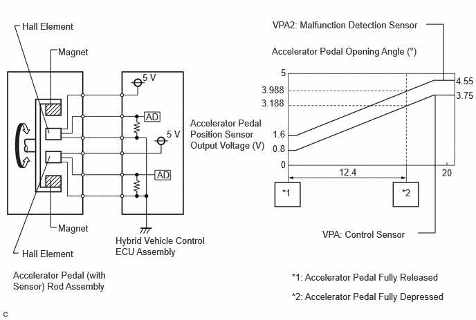
| DTC No. | Detection Item | DTC Detection Condition | Trouble Area | MIL | Warning Indicate | Note |
|---|---|---|---|---|---|---|
| P212012 | Throttle/Pedal Position Sensor/Switch "D" Circuit Short to Auxiliary Battery | Short to +B in the main sensor circuit:
The main sensor voltage is 4.8 V or more for 2 seconds. (1 trip detection logic) |
·
Wire harness or connector ·
Accelerator pedal sensor assembly ·
Hybrid vehicle control ECU assembly |
Comes on | Master Warning:
Comes on |
SAE Code:
P2123 |
| P212014 | Throttle/Pedal Position Sensor/Switch "D" Circuit Short to Ground or Open | Open or short to ground in the main sensor circuit:
The main sensor voltage is 0.4 V or less for 0.5 seconds. (1 trip detection logic) |
·
Wire harness or connector ·
Accelerator pedal sensor assembly ·
Hybrid vehicle control ECU assembly |
Comes on | Master Warning:
Comes on |
SAE Code:
P2122 |
| P21201C | Throttle/Pedal Position Sensor/Switch "D" Voltage Out of Range | Internal malfunction in the main sensor:
Main sensor output changes rapidly (detected when there are no circuit malfunctions such as an open or short). (1 trip detection logic) |
·
Wire harness or connector ·
Accelerator pedal sensor assembly ·
Hybrid vehicle control ECU assembly |
Comes on | Master Warning:
Comes on |
SAE Code:
P2121 |
| P21201F | Throttle/Pedal Position Sensor/Switch "D" Circuit Intermittent | Main sensor circuit wiring malfunction or level is not stable:
Main sensor voltage is 0.4 V or less or 4.8 V or more for a certain period of time. (Both of the following conditions are met: The main sensor voltage is 0.4 V or less for a certain period of time and 4.8 V or more for a certain period of time.) (1 trip detection logic) |
·
Wire harness or connector ·
Accelerator pedal sensor assembly ·
Hybrid vehicle control ECU assembly |
Comes on | Master Warning:
Comes on |
SAE Code:
P2120 |
| P212512 | Throttle/Pedal Position Sensor/Switch "E" Circuit Short to Auxiliary Battery | Short to +B in the sub sensor circuit:
Main sensor is normal and sub sensor voltage is 4.8 V or more for 2 seconds. (1 trip detection logic) |
·
Wire harness or connector ·
Accelerator pedal sensor assembly ·
Hybrid vehicle control ECU assembly |
Comes on | Master Warning:
Comes on |
SAE Code:
P2128 |
| P212514 | Throttle/Pedal Position Sensor/Switch "E" Circuit Short to Ground or Open | Open or short to ground in the sub sensor circuit:
The sub sensor voltage is 1.2 V or less for 0.5 seconds. (1 trip detection logic) |
·
Wire harness or connector ·
Accelerator pedal sensor assembly ·
Hybrid vehicle control ECU assembly |
Comes on | Master Warning:
Comes on |
SAE Code:
P2127 |
| P21251C | Throttle/Pedal Position Sensor/Switch "E" Voltage Out of Range | Internal malfunction of the sub sensor:
Sub sensor output changes rapidly (detected when there are no circuit malfunctions such as an open or short). (1 trip detection logic) |
·
Wire harness or connector ·
Accelerator pedal sensor assembly ·
Hybrid vehicle control ECU assembly |
Comes on | Master Warning:
Comes on |
SAE Code:
P2126 |
| P21251F | Throttle/Pedal Position Sensor/Switch "E" Circuit Intermittent | Sub sensor circuit wiring malfunction or level is not stable:
When the main sensor circuit is normal, the sub sensor voltage is 1.2 V or less or 4.8 V or more for a certain period of time. (Both of the following conditions are met: Sub sensor voltage is 1.2 V or less for a certain period of time, and the main sensor is normal and sub sensor voltage is 4.8 V or more for a certain period of time.) (1 trip detection logic) |
·
Wire harness or connector ·
Accelerator pedal sensor assembly ·
Hybrid vehicle control ECU assembly |
Comes on | Master Warning:
Comes on |
SAE Code:
P2125 |
| P213800 | Throttle/Pedal Position Sensor/Switch "D"/" E" Voltage Correlation | Difference between the main sensor value and sub sensor value is large.
(1 trip detection logic) |
·
Wire harness or connector ·
Accelerator pedal sensor assembly ·
Hybrid vehicle control ECU assembly |
Comes on | Master Warning:
Comes on |
SAE Code:
P2138 |
| P21382B | Throttle/Pedal Position Sensor/Switch "D"/"E" Signal Cross Coupled | Main or sub sensor circuit wiring malfunction:
The difference in voltage between the main sensor and sub sensor is 0.02 V or less, or a low output malfunction continues in both the main and sub sensors for a certain period of time. (1 trip detection logic) |
·
Wire harness or connector ·
Accelerator pedal sensor assembly ·
Hybrid vehicle control ECU assembly |
Comes on | Master Warning:
Comes on |
SAE Code:
P2138 |
| DTC No. | Data List |
|---|---|
| P212012 | ·
Accelerator Position Sensor No. 1 Voltage % ·
Accelerator Position Sensor No. 2 Voltage % |
| P212014 | |
| P21201C | |
| P21201F | |
| P212512 | |
| P212514 | |
| P21251C | |
| P21251F | |
| P213800 | |
| P21382B |
CONFIRMATION DRIVING PATTERN
- HINT:
- ·
After repair has been completed, clear the DTC and then check that the vehicle has returned to normal by performing the following All Readiness check procedure.
·When clearing the permanent DTCs, refer to the "CLEAR PERMANENT DTC" procedure.
Connect the GTS to the DLC3.
Turn the power switch on (IG) and turn the GTS on.
Clear the DTCs (even if no DTCs are stored, perform the clear DTC procedure).
Turn the power switch off and wait for 2 minutes or more.
Turn the power switch on (IG) and turn the GTS on.
Wait for approximately 10 seconds with the power switch on (READY) and shift lever in P, then fully depress and release the accelerator pedal several times.[*1]
- HINT:
-
[*1]: Normal judgment procedure.
-
The normal judgment procedure is used to complete DTC judgment and also used when clearing permanent DTCs.
Enter the following menus: Powertrain / Hybrid Control / Utility / All Readiness.
Check the DTC judgment result.
- HINT:
- ·
If the judgment result shows NORMAL, the system is normal.
·If the judgment result shows ABNORMAL, the system has a malfunction.
·If the judgment result shows INCOMPLETE, perform the normal judgment procedure again.
WIRING DIAGRAM
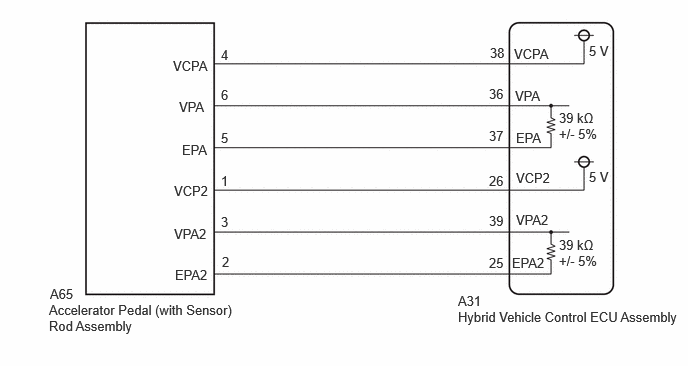
PROCEDURE
Connect the GTS to the DLC3.
Turn the power switch on (IG).
Enter the following menus: Powertrain / Hybrid Control / Data List / Accelerator Position Sensor No. 1 Voltage %, Accelerator Position Sensor No. 2 Voltage %.
- Powertrain > Hybrid Control > Data List
-
Tester Display Accelerator Position Sensor No.1 Voltage % Accelerator Position Sensor No.2 Voltage % - 50003 397 23,24
Read the Data List.
- Standard:
Tester Display Accelerator Pedal Condition Specified Condition Accelerator Position Sensor No. 1 Voltage % Not depressed 10 to 22% Fully depressed 52 to 90% Not depressed → Fully depressed → Not depressed (Accelerator pedal should be operated slowly) Value changes progressively Accelerator Position Sensor No. 2 Voltage % Not depressed 24 to 40% Fully depressed 68 to 99% Not depressed → Fully depressed → Not depressed (Accelerator pedal should be operated slowly) Value changes progressively
Turn the power switch off.
- Result:
Proceed to OK NG
OK
NG
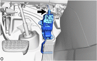
Check the connector connections and contact pressure of the relevant terminals for the accelerator pedal (with sensor) rod assembly connector.
- OK:
The connectors are connected securely and there are no contact pressure problems.
- Result:
Proceed to OK NG
OK
NG
- Result:
Proceed to OK NG
OK
NG
Disconnect the A65 accelerator pedal (with sensor) rod assembly connector.
Turn the power switch on (IG).
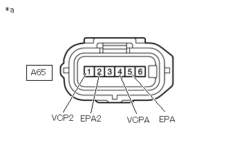
| *a | Front view of wire harness connector
(to Accelerator Pedal (with Sensor) Rod Assembly) |
Measure the voltage according to the value(s) in the table below.
- Standard Voltage:
Tester Connection Condition Specified Condition A65-4 (VCPA) - A65-5 (EPA) Power switch on (IG) 4.5 to 5.5 V A65-1 (VCP2) - A65-2 (EPA2) Power switch on (IG) 4.5 to 5.5 V
Turn the power switch off.
Reconnect the A65 accelerator pedal (with sensor) rod assembly connector.
- Result:
Proceed to OK NG
OK
NG
Disconnect the A65 accelerator pedal (with sensor) rod assembly connector.
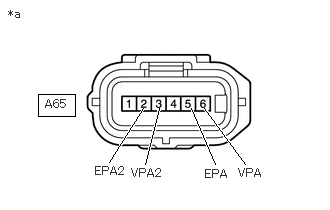
| *a | Front view of wire harness connector
(to Accelerator Pedal (with Sensor) Rod Assembly) |
Measure the resistance according to the value(s) in the table below.
- Standard Resistance:
Tester Connection Condition Specified Condition A65-6 (VPA) - A65-5 (EPA) Power switch off 28.00 to 41.61 kΩ A65-3 (VPA2) - A65-2 (EPA2) Power switch off 28.00 to 41.61 kΩ
Reconnect the A65 accelerator pedal (with sensor) rod assembly connector.
- Result:
Proceed to OK NG
OK
NG
Disconnect the A31 hybrid vehicle control ECU assembly connector.
Disconnect the A65 accelerator pedal (with sensor) rod assembly connector.
Turn the power switch on (IG).
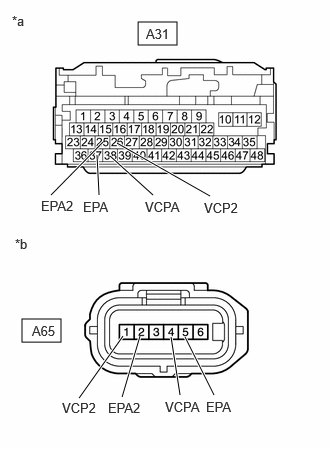
| *a | Front view of wire harness connector
(to Hybrid Vehicle Control ECU Assembly) |
| *b | Front view of wire harness connector
(to Accelerator Pedal (with Sensor) Rod Assembly) |
Measure the voltage according to the value(s) in the table below.
- Standard Voltage:
Tester Connection Condition Specified Condition A31-38 (VCPA) - Body ground Power switch on (IG) Below 1 V A31-37 (EPA) - Body ground Power switch on (IG) Below 1 V A31-26 (VCP2) - Body ground Power switch on (IG) Below 1 V A31-25 (EPA2) - Body ground Power switch on (IG) Below 1 V
- NOTICE:
-
Turning the power switch on (IG) with the hybrid vehicle control ECU assembly connector disconnected causes other DTCs to be stored. Clear the DTCs after performing this inspection.
Turn the power switch off.
Measure the resistance according to the value(s) in the table below.
- Standard Resistance (Check for Open):
Tester Connection Condition Specified Condition A31-38 (VCPA) - A65-4 (VCPA) Power switch off Below 1 Ω A31-37 (EPA) - A65-5 (EPA) Power switch off Below 1 Ω A31-26 (VCP2) - A65-1 (VCP2) Power switch off Below 1 Ω A31-25 (EPA2) - A65-2 (EPA2) Power switch off Below 1 Ω
- Standard Resistance (Check for Short):
Tester Connection Condition Specified Condition A31-38 (VCPA) or A65-4 (VCPA) - Body ground and other terminals Power switch off 10 kΩ or higher A31-37 (EPA) or A65-5 (EPA) - Body ground and other terminals Power switch off 10 kΩ or higher A31-26 (VCP2) or A65-1 (VCP2) - Body ground and other terminals Power switch off 10 kΩ or higher A31-25 (EPA2) or A65-2 (EPA2) - Body ground and other terminals Power switch off 10 kΩ or higher
Reconnect the A65 accelerator pedal (with sensor) rod assembly connector.
Reconnect the A31 hybrid vehicle control ECU assembly connector.
- Result:
Proceed to OK NG
OK
NG
Disconnect the A31 hybrid vehicle control ECU assembly connector.
Disconnect the A65 accelerator pedal (with sensor) rod assembly connector.
Turn the power switch on (IG).
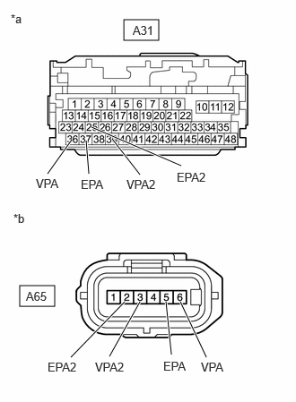
| *a | Front view of wire harness connector
(to Hybrid Vehicle Control ECU Assembly) |
| *b | Front view of wire harness connector
(to Accelerator Pedal (with Sensor) Rod Assembly) |
Measure the voltage according to the value(s) in the table below.
- Standard Voltage:
Tester Connection Condition Specified Condition A31-36 (VPA) - Body ground Power switch on (IG) Below 1 V A31-39 (VPA2) - Body ground Power switch on (IG) Below 1 V A31-37 (EPA) - Body ground Power switch on (IG) Below 1 V A31-25 (EPA2) - Body ground Power switch on (IG) Below 1 V
- NOTICE:
-
Turning the power switch on (IG) with the hybrid vehicle control ECU assembly connector disconnected causes other DTCs to be stored. Clear the DTCs after performing this inspection.
Turn the power switch off.
Measure the resistance according to the value(s) in the table below.
- Standard Resistance (Check for Open):
Tester Connection Condition Specified Condition A31-36 (VPA) - A65-6 (VPA) Power switch on (IG) Below 1 Ω A31-37 (EPA) - A65-5 (EPA) Power switch on (IG) Below 1 Ω A31-39 (VPA2) - A65-3 (VPA2) Power switch on (IG) Below 1 Ω A31-25 (EPA2) - A65-2 (EPA2) Power switch on (IG) Below 1 Ω
- Standard Resistance (Check for Short):
Tester Connection Condition Specified Condition A31-36 (VPA) or A65-6 (VPA) - Body ground and other terminals Power switch on (IG) 10 kΩ or higher A31-37 (EPA) or A65-5 (EPA) - Body ground and other terminals Power switch on (IG) 10 kΩ or higher A31-39 (VPA2) or A65-3 (VPA2) - Body ground and other terminals Power switch on (IG) 10 kΩ or higher A31-25 (EPA2) or A65-2 (EPA2) - Body ground and other terminals Power switch on (IG) 10 kΩ or higher
Reconnect the A65 accelerator pedal (with sensor) rod assembly connector.
Reconnect the A31 hybrid vehicle control ECU assembly connector.
- Result:
Proceed to OK NG
OK
NG