HYBRID / BATTERY CONTROL HYBRID CONTROL SYSTEM P1C8449 High Voltage Power Resource Circuit Short during Ready ON
DTC SUMMARY
MALFUNCTION DESCRIPTION
The hybrid vehicle control ECU assembly monitors the high-voltage wiring between the HV battery and inverter with converter assembly and detects an open circuit malfunction.
- HINT:
- ·
This DTC is differentiated from P300449 based on detection timing (after power switch is turned on (READY)). If P300449 is also output at the same time, first perform troubleshooting for P300449.
·If there is a SMRG stuck open malfunction, only P1C8449 is output.
The cause of this malfunction may be one of the following:
Voltage sensor (VH or VL) malfunction
Motor generator control ECU (MG ECU) malfunction
Communication (wire harness) malfunction
HV battery malfunction
HV battery junction block assembly malfunction
Inverter with converter assembly malfunction
High-voltage wire harness malfunction
High-voltage connector or connection malfunction
Hybrid vehicle control ECU assembly malfunction
HV battery junction block assembly malfunction
Low voltage wire harness malfunction
Low voltage connector malfunction
DESCRIPTION
Refer to the description for DTC P0AE411.
| DTC No. | Detection Item | DTC Detection Condition | Trouble Area | MIL | Warning Indicate | Note |
|---|---|---|---|---|---|---|
| P1C8449 | High Voltage Power Resource Circuit Short during Ready ON | High-voltage circuit malfunctions between the HV battery and inverter with converter assembly.
The voltage before boosting continues to be out of the HV battery voltage range or the integrated value of variation amount of the voltage before boosting for a specified period of time is large while the power switch is on (READY). The EV electric battery fuse in the service plug grip is blown, the service plug grip is removed, SMRB or SMRG remains open, or the high-voltage cable has an open circuit. (1 trip detection logic) |
·
HV battery junction block assembly ·
Wire harness or connector ·
Hybrid vehicle control ECU assembly |
Comes on | Master Warning:
Comes on |
SAE Code:
P3004 |
| DTC No. | Data List |
|---|---|
| P1C8449 | ·
Hybrid/EV Battery Voltage ·
Hybrid/EV Battery Current ·
VL-Voltage before Boosting ·
VH-Voltage after Boosting |
The following items can be helpful when performing repairs:
Ready Signal
CONFIRMATION DRIVING PATTERN
- HINT:
- ·
After repair has been completed, clear the DTC and then check that the vehicle has returned to normal by performing the following All Readiness check procedure.
·When clearing the permanent DTCs, refer to the "CLEAR PERMANENT DTC" procedure.
Connect the GTS to the DLC3.
Turn the power switch on (IG) and turn the GTS on.
Clear the DTCs (even if no DTCs are stored, perform the clear DTC procedure).
Turn the power switch off and wait for 2 minutes or more.
Turn the power switch on (IG) and turn the GTS on.
Turn the power switch on (READY) and wait for 3 minutes or more. [*1]
- HINT:
- ·
According to the display on the GTS, read the Data List and monitor the values of "Hybrid/EV Battery Voltage" and "VL-Voltage before Boosting" for 3 minutes. If the difference between "Hybrid/EV Battery Voltage" and "VL-Voltage before Boosting" is always less than 50 V, the vehicle has returned to normal.
·[*1]: Normal judgment procedure.
The normal judgment procedure is used to complete DTC judgment and also used when clearing permanent DTCs.
Enter the following menus: Powertrain / Hybrid Control / Utility / All Readiness.
Check the DTC judgment result.
- HINT:
- ·
If the judgment result shows NORMAL, the system is normal.
·If the judgment result shows ABNORMAL, the system has a malfunction.
·If the judgment result shows INCOMPLETE, perform the normal judgment procedure again.
WIRING DIAGRAM
Refer to the wiring diagram for the HV battery high-voltage line circuit.
CAUTION / NOTICE / HINT
- CAUTION:
-
Refer to the precautions before inspecting high voltage circuit.
PROCEDURE
Connect the GTS to the DLC3.
Turn the power switch on (IG).
Enter the following menus: Powertrain / Hybrid Control, Motor Generator and HV Battery / Trouble Codes.
Check for DTCs.
- Powertrain > Hybrid Control > Trouble Codes
- 50001 397
- Powertrain > Motor Generator > Trouble Codes
- 50001 395
- Powertrain > HV Battery > Trouble Codes
- 50001 398
- Result:
Result Proceed to P1C8449 only is output, or P0A9563 and DTCs except the ones in the table below are also output. A DTCs of hybrid control system in the tables below are output. B DTCs of motor generator control system in the tables below are output. C DTCs of hybrid battery system in the tables below are output. D P0A9563 is also output. E
| Malfunction Content | System | Relevant DTC | |
|---|---|---|---|
| Microcomputer malfunction | Hybrid control system | P0A1B49 | Drive Motor "A" Control Module Internal Electronic Failure |
| P060647 | Hybrid/EV Powertrain Control Module Processor Watchdog / Safety MCU Failure | ||
| Motor generator control system | P0A1B1F | Generator Control Module Circuit Intermittent | |
| P0A1A47 | Generator Control Module Watchdog / Safety μC Failure | ||
| P0A1A49 | Generator Control Module Internal Electronic Failure | ||
| P1C2A1C | Generator A/D Converter Circuit Circuit Voltage Out of Range | ||
| P1C2A49 | Generator A/D Converter Circuit Internal Electronic Failure | ||
| P313383 | Communication Error from Generator to Drive Motor "A" Value of Signal Protection Calculation Incorrect | ||
| P313386 | Communication Error from Generator to Drive Motor "A" Signal Invalid | ||
| Hybrid battery system | P060687 | Hybrid/EV Battery Energy Control Module Processor to Monitoring Processor Missing Message | |
| P060A47 | Hybrid/EV Battery Energy Control Module Monitoring Processor Watchdog / Safety MCU Failure | ||
| P060A87 | Hybrid/EV Battery Energy Control Module Processor from Monitoring Processor Missing Message | ||
| P060B16 | Hybrid/EV Battery Energy Control Module A/D Processing Circuit Voltage Below Threshold | ||
| P060B49 | Hybrid/EV Battery Energy Control Module A/D Processing Internal Electronic Failure | ||
| Power source circuit malfunction | Motor generator control system | P06D61C | Generator Control Module Offset Power Circuit Voltage Out of Range |
| Hybrid battery system | P1CBB12 | Hybrid/EV Battery Current Sensor Power Supply Circuit Short to Auxiliary Battery | |
| P1CBB14 | Hybrid/EV Battery Current Sensor Power Supply Circuit Short to Ground or Open | ||
| Communication system malfunction | Hybrid control system | P312387 | Lost Communication with Drive Motor Control Module "A" from Hybrid/EV Control Module Missing Message |
| U011187 | Lost Communication with Hybrid/EV Battery Energy Control Module "A" Missing Message | ||
| Motor generator control system | P313387 | Communication Error from Generator to Drive Motor "A" Missing Message | |
| Sensor and actuator circuit malfunction | Hybrid control system | P0ABF00 | Hybrid/EV Battery Current Sensor "A" Circuit Range/Performance |
| P0AD911 | Hybrid/EV Battery Positive Contactor Circuit Short to Ground | ||
| P0AD915 | Hybrid/EV Battery Positive Contactor Circuit Short to Auxiliary Battery or Open | ||
| P0ADD11 | Hybrid/EV Battery Negative Contactor Circuit Short to Ground | ||
| P0ADD15 | Hybrid/EV Battery Negative Contactor Circuit Short to Auxiliary Battery or Open | ||
| Motor generator control system | P0D2D16 | Drive Motor "A" Inverter Voltage Sensor(VH) Circuit Voltage Below Threshold | |
| P0D2D17 | Drive Motor "A" Inverter Voltage Sensor(VH) Circuit Voltage Above Threshold | ||
| Hybrid battery system | P0ABF11 | Hybrid/EV Battery Current Sensor "A" Circuit Short to Ground | |
| P0ABF15 | Hybrid/EV Battery Current Sensor "A" Circuit Short to Auxiliary Battery or Open | ||
| P0ABF28 | Hybrid/EV Battery Current Sensor "A" Signal Bias Level Out of Range / Zero Adjustment Failure | ||
| P0ABF2A | Hybrid/EV Battery Current Sensor "A" Signal Stuck In Range | ||
| P0B0E11 | Hybrid/EV Battery Current Sensor "B" Circuit Short to Ground | ||
| P0B0E15 | Hybrid/EV Battery Current Sensor "B" Circuit Short to Auxiliary Battery or Open | ||
| P0B1362 | Hybrid/EV Battery Current Sensor "A"/"B" Signal Compare Failure | ||
| System malfunction | Hybrid control system | P0A1F94 | Hybrid/EV Battery Energy Control Module Unexpected Operation |
| P0D2D1C | Drive Motor "A" Inverter Voltage Sensor Voltage Out of Range | ||
| P0E311C | Boosting Converter Voltage Sensor "A" Voltage Out of Range | ||
| P1C8349 | High Voltage Power Resource Circuit Voltage Sensor after Boosting Malfunction | ||
| P300449 | High Voltage Power Resource Circuit Short during Pre-Charge | ||
| Motor generator control system | P1CB69E | Drive Motor "A" Inverter Voltage Sensor(VH) Stuck On | |
| P0CA300 | DC/DC Converter Step Up Voltage Performance | ||
- HINT:
- ·
P1C8449 may be output as a result of the malfunction indicated by the DTCs above.
(a)The chart above is listed in inspection order of priority.
(b)Check DTCs that are output at the same time by following the listed order. (The main cause of the malfunction can be determined without performing unnecessary inspections.)
Turn the power switch off.
A
B
C
for 2WD:
for AWD:
D
E
- Result:
Proceed to NEXT
NEXT
Connect the GTS to the DLC3.
With the vehicle stopped, apply the parking brake and turn the power switch on (READY).
- NOTICE:
-
Perform this test with the AUTO function (shift-linked function) of the electric parking brake system off.
- HINT:
- ·
If the power switch could not be turned on (READY), turn the power switch off and check for DTCs after turning the power switch on (READY) again.
·Because P300449 uses 2 trip detection logic, the DTC detection conditions need to be met 2 times.
·When the parking brake indicator (red) is illuminated after the electric parking brake switch assembly has been pulled to the lock side, the maximum amount of braking force is applied if the electric parking brake switch assembly is pulled to the lock side one more time.
Ensure the safety of the areas in front and at the back of the vehicle.
Move the shift lever to D and depress both the accelerator pedal and brake pedal at the same time.
- HINT:
-
Depressing both the accelerator pedal and brake pedal at the same time causes the HV battery current to flow and ensures that there is no problem with the high-voltage wiring.
Enter the following menus: Powertrain / Hybrid Control / Trouble Codes.
Check for DTCs.
- Powertrain > Hybrid Control > Trouble Codes
- 50001 397
- Result:
Result Proceed to P1C8449 is output, or no DTCs are output. A Power switch could not be turned on (READY) and DTC P300449 is output. B
Turn the power switch off.
A
B
- Result:
Proceed to OK NG
OK
NG
- Result:
Result Proceed to OK A NG (The connector is not connected securely.) B NG (The terminals are not making secure contact or are deformed, or water or foreign matter exists in the connector.) C
A
B
C
- Result:
Proceed to OK NG
OK
NG
- CAUTION:
-
Be sure to wear insulated gloves.
Check that the service plug grip is not installed.
- NOTICE:
-
After removing the service plug grip, do not turn the power switch on (READY), unless instructed by the repair manual because this may cause a malfunction.
Remove the No. 1 HV battery cover panel RH.
Disconnect the M32 HV battery junction block assembly connector.
Disconnect the A30 hybrid vehicle control ECU assembly connector.
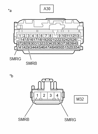
| *a | Front view of wire harness connector
(to Hybrid Vehicle Control ECU Assembly) |
| *b | Front view of wire harness connector
(to HV Battery Junction Block Assembly) |
Measure the resistance according to the value(s) in the table below.
- Standard Resistance:
Tester Connection Condition Specified Condition A30-2 (SMRB) - M32-1 (SMRB) Power switch off Below 1 Ω A30-27 (SMRG) - M32-4 (SMRG) Power switch off Below 1 Ω
Reconnect the A30 hybrid vehicle control ECU assembly connector.
Reconnect the M32 HV battery junction block assembly connector.
Install the No. 1 HV battery cover panel RH.
- Result:
Proceed to OK NG
OK
NG
- CAUTION:
-
Be sure to wear insulated gloves.
Check that the service plug grip is not installed.
- NOTICE:
-
After removing the service plug grip, do not turn the power switch on (READY), unless instructed by the repair manual because this may cause a malfunction.
Remove the No. 1 HV battery cover panel RH.
Disconnect the M32 HV battery junction block assembly connector.
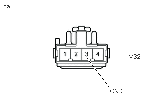
| *a | Front view of wire harness connector
(to HV Battery Junction Block Assembly) |
Measure the resistance according to the value(s) in the table below.
- Standard Resistance:
Tester Connection Condition Specified Condition M32-3 (GND) - Body ground Power switch off Below 1 Ω
Reconnect the M32 HV battery junction block assembly connector.
Install the No. 1 HV battery cover panel RH.
- Result:
Proceed to OK NG
OK
NG
- Result:
Proceed to NEXT
NEXT
- CAUTION:
-
Be sure to wear insulated gloves.
Install the service plug grip.
Turn the power switch on (IG).
Turn the power switch off and wait for 2 minutes or more.
Turn the power switch on (READY).
Enter the following menus: Powertrain / Hybrid Control / Data List / Hybrid/EV Battery Voltage, VL-Voltage before Boosting.
According to the display on the GTS, read the Data List and monitor the values of "Hybrid/EV Battery Voltage" and "VL-Voltage before Boosting" for 3 minutes.
- Powertrain > Hybrid Control > Data List
-
Tester Display VL-Voltage before Boosting Hybrid/EV Battery Voltage - 50003 397 150,227
- Result:
Result Proceed to Difference between "Hybrid/EV Battery Voltage" and "VL-Voltage before Boosting" is always less than 50 V. A Difference between "Hybrid/EV Battery Voltage" and "VL-Voltage before Boosting" is 50 V or more. B
Turn the power switch off.
A
B