HYBRID / BATTERY CONTROL HYBRID CONTROL SYSTEM P0C7396 Motor Electronics Coolant Pump "A" Component Internal Failure
DTC SUMMARY
MALFUNCTION DESCRIPTION
This DTC is stored when the inverter water pump assembly is malfunctioning. The cause of this malfunction may be one of the following:
Inverter water pump assembly internal malfunction
Open or short in wire harness
Improperly connected connector
Foreign matter in inverter water pump assembly
Hybrid cooling system coolant is frozen
- HINT:
-
If this DTC is stored, the driving torque may be restricted.
DESCRIPTION
The inverter water pump assembly transmits rotation speed information to the hybrid vehicle control ECU assembly. The hybrid vehicle control ECU assembly monitors the speed and detects malfunctions.
| DTC No. | Detection Item | DTC Detection Condition | Trouble Area | MIL | Warning Indicate | Note |
|---|---|---|---|---|---|---|
| P0C7396 | Motor Electronics Coolant Pump "A" Component Internal Failure | The inverter water pump assembly revolution speed is abnormally high or low (or stopped) for 1 minute or more.
(1 trip detection logic) |
·
Inverter cooling system ·
Wire harness or connector ·
Inverter water pump assembly ·
Hybrid vehicle control ECU assembly |
Comes on | Master Warning:
Comes on |
SAE Code:
P0C73 |
- HINT:
-
The inverter water pump assembly operates when the power switch is on (READY).
| DTC No. | Data List |
|---|---|
| P0C7396 | ·
Inverter Water Pump Revolution ·
Inverter Water Pump Duty Ratio ·
Inverter Coolant Water Temperature |
| DTC No. | Active Test |
|---|---|
| P0C7396 | Activate the Inverter Water Pump |
CONFIRMATION DRIVING PATTERN
- HINT:
- ·
After repair has been completed, clear the DTC and then check that the vehicle has returned to normal by performing the following All Readiness check procedure.
·When clearing the permanent DTCs, refer to the "CLEAR PERMANENT DTC" procedure.
Connect the GTS to the DLC3.
Turn the power switch on (IG) and turn the GTS on.
Clear the DTCs (even if no DTCs are stored, perform the clear DTC procedure).
Turn the power switch off and wait for 2 minutes or more.
Turn the power switch on (IG) and turn the GTS on.
Turn the power switch on (READY). [*1]
Wait for 2 minutes or more. [*2]
- HINT:
-
[*1] to [*2] : Normal judgment procedure.
-
The normal judgment procedure is used to complete DTC judgment and also used when clearing permanent DTCs.
Enter the following menus: Powertrain / Hybrid Control / Utility / All Readiness.
Check the DTC judgment result.
- HINT:
- ·
If the judgment result shows NORMAL, the system is normal.
·If the judgment result shows ABNORMAL, the system has a malfunction.
·If the judgment result shows INCOMPLETE, perform the normal judgment procedure again.
WIRING DIAGRAM
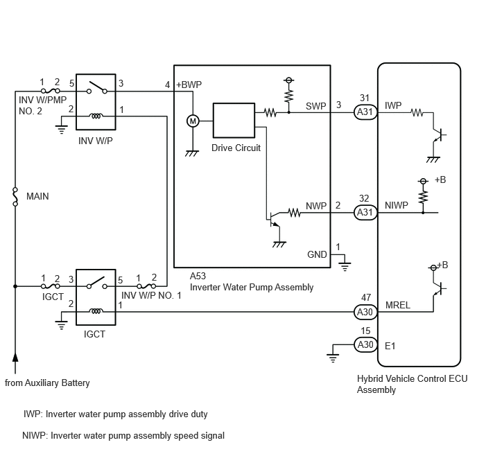
CAUTION / NOTICE / HINT
- NOTICE:
-
If this vehicle is jump started, etc. and excessive voltage is applied to the auxiliary battery, the inverter water pump assembly may suspend control as a self-protection function and store DTCs.
-
(When the auxiliary battery voltage returns to normal, the inverter water pump assembly will resume normal operation. In this case it is not necessary to replace the inverter water pump assembly.)
PROCEDURE
Connect the GTS to the DLC3.
Turn the power switch on (IG).
Enter the following menus: Powertrain / Hybrid Control / Trouble Codes.
Check for DTCs.
- Powertrain > Hybrid Control > Trouble Codes
- 50001 397
- Result:
Result Proceed to P0C7396 only is output, or DTCs except the ones in the table below are also output. A Any of the following DTCs including pending DTCs are also output. B
| Malfunction Content | Relevant DTC | |
|---|---|---|
| Microcomputer malfunction | P060647 | Hybrid/EV Powertrain Control Module Processor Watchdog / Safety MCU Failure |
| P06881F | ECM/PCM Power Relay Sense Circuit Intermittent | |
| Sensor and actuator circuit malfunction | P314A31 | Motor Electronics Coolant Pump "A" No Signal |
- HINT:
-
P0C7396 may be output as a result of the malfunction indicated by the DTCs above.
- 1.
The chart above is listed in inspection order of priority.
2.Check DTCs that are output at the same time by following the listed order. (The main cause of the malfunction can be determined without performing unnecessary inspections.)
Turn the power switch off.
A
B
- NOTICE:
-
Be sure to perform the inspection with the auxiliary battery voltage at 11 V or more.
- HINT:
- ·
When the auxiliary battery voltage is low, the inverter water pump assembly may not operate.
·When the inverter water pump assembly signal line (SWP - IWP) is open or its connection is faulty, the inverter water pump assembly is operated forcibly.
Connect the GTS to the DLC3.
Turn the power switch on (IG).
Enter the following menus: Powertrain / Hybrid Control / Data List / Inverter Water Pump Revolution.
- Powertrain > Hybrid Control > Data List
-
Tester Display Inverter Water Pump Revolution - 50003 397 60
According to the display on the GTS, read the Data List.
- OK:
Tester Display Condition Specified Condition Inverter Water Pump Revolution Power switch on (IG) 200 rpm or less
- HINT:
-
When the inverter water pump assembly is not operating, the Data List item "Inverter Water Pump Revolution" displays a value 200 rpm or less.
Turn the power switch off.
- Result:
Proceed to OK NG
OK
NG
- Result:
Proceed to NEXT
NEXT
- NOTICE:
- ·
Make sure that the HV coolant level is above the low line of the inverter reserve tank.
·Be sure to perform the inspection with the auxiliary battery voltage at 11 V or more.
- HINT:
-
When the auxiliary battery voltage is low, the inverter water pump assembly may not operate.
Connect the GTS to the DLC3.
Turn the power switch on (IG).
Enter the following menus: Powertrain / Hybrid Control / Active Test / Activate the Inverter Water Pump.
Select the Data List item "Inverter Water Pump Revolution".
- Powertrain > Hybrid Control > Active Test
-
Active Test Display Activate the Inverter Water Pump -
Data List Display Inverter Water Pump Revolution - 50004 397 1 60
According to the display on the GTS, perform the Active Test "Activate the Inverter Water Pump" and, check the value of the Data List item "Inverter Water Pump Revolution".
- OK:
Tester Display Condition Specified Condition Inverter Water Pump Revolution Power switch on (IG)
During Active Test3000 to 9500 rpm
- HINT:
- ·
Perform the Active Test with the inverter coolant temperature between -15 and 65°C (5 to 149°F).
·When the inverter water pump assembly is not operating, the Data List item "Inverter Water Pump Revolution" displays a value 200 rpm or less.
Turn the power switch off.
- Result:
Proceed to OK NG
OK
NG
- Result:
Result Proceed to Ambient Temperature value is above freezing temperature of the HV coolant. A Ambient Temperature value is below freezing temperature of the HV coolant. B
A
B
- Result:
Proceed to OK NG
OK
NG
- Result:
Proceed to OK NG
OK
NG
Disconnect the A31 hybrid vehicle control ECU assembly connector.
Disconnect the A53 inverter water pump assembly connector.
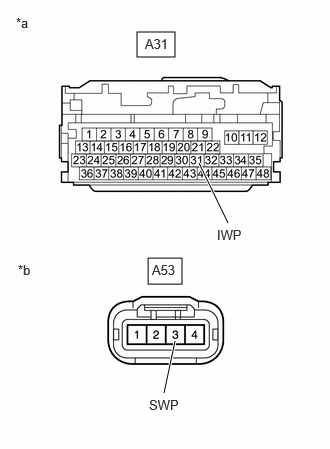
| *a | Front view of wire harness connector
(to Hybrid Vehicle Control ECU Assembly) |
| *b | Front view of wire harness connector
(to Inverter Water Pump Assembly) |
Measure the resistance according to the value(s) in the table below.
- Standard Resistance (Check for Open):
Tester Connection Condition Specified Condition A31-31 (IWP) - A53-3 (SWP) Power switch off Below 1 Ω
- Standard Resistance (Check for Short):
Tester Connection Condition Specified Condition A31-31 (IWP) or A53-3 (SWP) - Body ground and other terminals Power switch off 10 kΩ or higher
- HINT:
-
Check the condition (looseness, deterioration, etc.) of the wire to body ground for the inverter water pump assembly.
Reconnect the A53 inverter water pump assembly connector.
Reconnect the A31 hybrid vehicle control ECU assembly connector.
- Result:
Proceed to OK NG
OK
NG
- NOTICE:
-
Be sure to perform the inspection with the auxiliary battery voltage at 11 V or more.
- HINT:
-
When the auxiliary battery voltage is low, the inverter water pump assembly may not operate.
Connect the GTS to the DLC3.
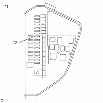
| *1 | No. 1 Engine Room Relay Block and Junction Block Assembly |
| *2 | INV W/PMP NO. 2 Fuse |
Remove the INV W/PMP NO. 2 fuse from No. 1 engine room relay block and junction block assembly.
Turn the power switch on (IG).
Enter the following menus: Powertrain / Hybrid Control / Data List / Inverter Water Pump Revolution.
- Powertrain > Hybrid Control > Data List
-
Tester Display Inverter Water Pump Revolution - 50003 397 60
According to the display on the GTS, read the Data List.
- OK:
Tester Display Condition Specified Condition Inverter Water Pump Revolution Power switch on (IG) 200 rpm or less
Turn the power switch off.
Install the INV W/PMP NO. 2 fuse.
- Result:
Proceed to OK NG
OK
NG
Disconnect the A31 hybrid vehicle control ECU assembly connector.
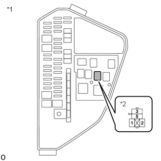
| *1 | No. 1 Engine Room Relay Block and Junction Block Assembly |
| *2 | INV W/P Relay Holder |
Remove the INV W/P relay from No. 1 engine room relay block and junction block assembly.
Connect terminals 3 and 5 of the INV W/P relay holder.
- HINT:
-
Make a short circuit between terminals 3 and 5 to supply +B voltage to the inverter water pump.
Measure the voltage according to the value(s) in the table below.
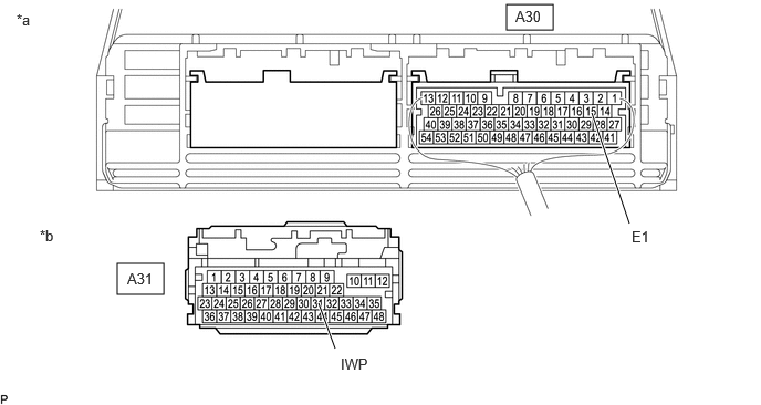
| *a | Component with harness connected
(Hybrid Vehicle Control ECU Assembly) |
*b | Front view of wire harness connector
(to Hybrid Vehicle Control ECU Assembly) |
- Standard Voltage:
Tester Connection Condition Specified Condition A31-31 (IWP) - A30-15 (E1) INV W/P relay holder terminals 3 and 5 connected
Power switch off11 to 14 V
- NOTICE:
-
Make sure to check for and clear DTCs after performing this inspection.
Install the INV W/P relay.
Reconnect the A31 hybrid vehicle control ECU assembly connector.
- Result:
Proceed to OK NG
OK
NG
Connect an oscilloscope between the hybrid vehicle control ECU assembly terminals specified in the table below.
Turn the power switch on (IG).
Check the waveform while turning the power switch on (IG).
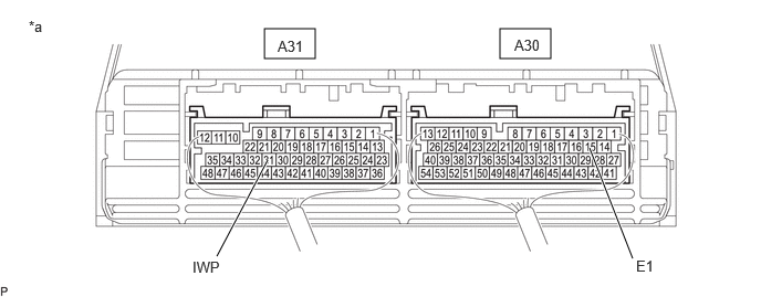
| *a | Component with harness connected
(Hybrid Vehicle Control ECU Assembly) |
- | - |
| Item | Content |
|---|---|
| Terminal | A31-31 (IWP) - A30-15 (E1) |
| Equipment Setting | 5 V/DIV., 50 ms./DIV. |
| Condition | Power switch on (IG) |
- OK:
Waveform duty ratio is between 3% and 9%.
Turn the power switch off.
- Result:
Proceed to OK NG
OK
NG
- Result:
Proceed to NEXT
NEXT
After replacing the inverter water pump assembly, add HV coolant and perform air bleeding.
- Result:
Proceed to NEXT
NEXT