M20D-FKS ENGINE CONTROL SFI SYSTEM P062714 Fuel Pump "A" Control Circuit Short to Ground or Open
DESCRIPTION
Refer to DTC P062712.
| DTC No. | Detection Item | DTC Detection Condition | Trouble Area | MIL | Memory | Note |
|---|---|---|---|---|---|---|
| P062714 | Fuel Pump "A" Control Circuit Short to Ground or Open | When the fuel pump control ECU operation duty ratio is 3 to 65%, the FPC terminal voltage is a certain value or less for 3 seconds or more (1 trip detection logic). | ·
Open or short in fuel pump control ECU circuit ·
Fuel pump control ECU ·
EFI-MAIN NO. 2 relay ·
ECM |
Comes on | DTC stored | SAE: P0628 |
| DTC No. | Data List |
|---|---|
| P062714 | Fuel Pump Control Duty Ratio |
MONITOR DESCRIPTION
The ECM monitors the fuel pump control ECU operation signals.
When the output duty ratio of the operation signal from the ECM is 3 to 65% and the FPC terminal voltage is a certain value or less for 3 seconds or more, the ECM stores a DTC.
MONITOR STRATEGY
| Required Sensors/Components | Fuel pump control ECU |
| Frequency of Operation | Continuous |
CONFIRMATION DRIVING PATTERN
- HINT:
- ·
After repair has been completed, clear the DTC and then check that the vehicle has returned to normal by performing the following All Readiness check procedure.
·When clearing the permanent DTCs, refer to the "CLEAR PERMANENT DTC" procedure.
Connect the GTS to the DLC3.
Turn the ignition switch to ON.
Turn the GTS on.
Clear the DTCs (even if no DTCs are stored, perform the clear DTC procedure).
Turn the ignition switch off and wait for at least 30 seconds.
Start the engine and wait 10 seconds or more [A].
Turn the GTS on.
Enter the following menus: Powertrain / Engine / Trouble Codes [B].
Read the pending DTCs.
- HINT:
- ·
If a pending DTC is output, the system is malfunctioning.
·If a pending DTC is not output, perform the following procedure.
Enter the following menus: Powertrain / Engine / Utility / All Readiness.
Input the DTC: P062714.
Check the DTC judgment result.
| GTS Display | Description |
|---|---|
| NORMAL | ·
DTC judgment completed ·
System normal |
| ABNORMAL | ·
DTC judgment completed ·
System abnormal |
| INCOMPLETE | ·
DTC judgment not completed ·
Perform driving pattern after confirming DTC enabling conditions |
- HINT:
- ·
If the judgment result is NORMAL, the system is normal.
·If the judgment result is ABNORMAL, the system is malfunctioning.
·If the judgment result is INCOMPLETE, run the engine at an engine speed of 2000 rpm or more for 10 seconds or more and check the DTC judgment result again.
·[A] to [B]: Normal judgment procedure.
The normal judgment procedure is used to complete DTC judgment and also used when clearing permanent DTCs.
·When clearing the permanent DTCs, do not disconnect the cable from the battery terminal or attempt to clear the DTCs during this procedure, as doing so will clear the universal trip and normal judgment histories.
WIRING DIAGRAM
Refer to DTC P062712.
CAUTION / NOTICE / HINT
- NOTICE:
-
Inspect the fuses for circuits related to this system before performing the following procedure.
- HINT:
-
Read Freeze Frame Data using the GTS. The ECM records vehicle and driving condition information as Freeze Frame Data the moment a DTC is stored. When troubleshooting, Freeze Frame Data can help determine if the vehicle was moving or stationary, if the engine was warmed up or not, if the air fuel ratio was lean or rich, and other data from the time the malfunction occurred.
PROCEDURE
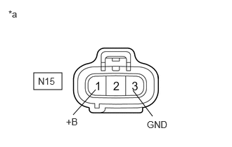
| *a | Front view of wire harness connector
(to Fuel Pump Control ECU) |
Disconnect the fuel pump control ECU connector.
Turn the ignition switch to ON.
Measure the voltage according to the value(s) in the table below.
- Standard Voltage:
Tester Connection Condition Specified Condition N15-1 (+B) - N15-3 (GND) Ignition switch ON 11 to 14 V
- Result:
Proceed to OK NG
OK
NG
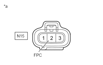
| *a | Front view of wire harness connector
(to Fuel Pump Control ECU) |
Disconnect the fuel pump control ECU connector.
Connect the GTS to the DLC3.
Turn the ignition switch to ON.
Turn the GTS on.
Enter the following menus: Powertrain / Engine / Active Test / Fuel Pump Single Phase Energization.
- Powertrain > Engine > Active Test
-
Tester Display Fuel Pump Single Phase Energization - 50004 372 49
Operate the fuel pump control ECU using the Active Test function and measure the resistance according to the value(s) in the table below.
- Standard Resistance:
Tester Connection GTS Operation Specified Condition N15-2 (FPC) - Body ground Before Active Test → During Active Test Before Active Test: Resistance is stable → During Active Test: Resistance fluctuates*
- HINT:
-
*: Using the Active Test, duty control of the transistors in the ECM will be performed. Due to the duty control, resistance of the FPC terminal will be unstable during the Active Test. If the resistance is stable before the Active Test and fluctuates while performing the Active Test, it can be determined that the transistor is operating. If the transistor does not operate during the Active Test, the ECM may be malfunctioning.
- Result:
Proceed to OK NG
OK
NG
Disconnect the fuel pump control ECU connector.
Disconnect the ECM connector.
Measure the resistance according to the value(s) in the table below.
- Standard Resistance:
Tester Connection Condition Specified Condition N15-2 (FPC) - A116-61 (FPC) Always Below 1 Ω N15-2 (FPC) or A116-61 (FPC) - Body ground Always 10 kΩ or higher
- Result:
Proceed to OK NG
OK
NG
Disconnect the fuel pump control ECU connector.
Measure the resistance according to the value(s) in the table below.
- Standard Resistance:
Tester Connection Condition Specified Condition N15-3 (GND) - Body ground Always Below 1 Ω
- Result:
Proceed to OK NG
OK
NG
Inspect the EFI-MAIN NO. 2 relay.
- Result:
Proceed to OK NG
OK
NG
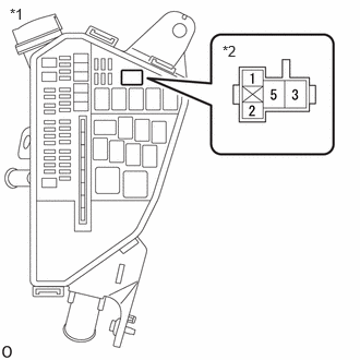
| *1 | No 1 Engine Room Relay Block and Junction Block Assembly |
| *2 | EFI-MAIN NO. 2 Relay |
Remove the EFI-MAIN NO. 2 relay from the No. 1 engine room relay block and junction block assembly.
Measure the voltage according to the value(s) in the table below.
- Standard Voltage:
Tester Connection Condition Specified Condition 3 (EFI-MAIN NO. 2 relay) - Body ground Always 11 to 14 V
- Result:
Proceed to OK NG
OK
NG
Remove the EFI-MAIN NO. 2 relay from the No. 1 engine room relay block and junction block assembly.
Measure the resistance according to the value(s) in the table below.
- Standard Resistance:
Tester Connection Condition Specified Condition 1 (EFI-MAIN NO. 2 relay) - Body ground Always Below 1 Ω
- Result:
Proceed to OK NG
OK
NG
Disconnect the fuel pump control ECU connector.
Remove the EFI-MAIN NO. 2 relay from the No. 1 engine room relay block and junction block assembly.
Measure the resistance according to the value(s) in the table below.
- Standard Resistance:
Tester Connection Condition Specified Condition N15-1 (+B) - 5 (EFI-MAIN NO. 2 relay) Always Below 1 Ω N15-1 (+B) or 5 (EFI-MAIN NO. 2 relay) - Body ground and other terminals Always 10 kΩ or higher
- Result:
Proceed to OK NG
OK
NG