RM36D0EC
_58
Vehicle Interior
_083105
POWER OUTLETS (INT)
_0584671
WIRELESS CHARGING SYSTEM
J
POWER OUTLETS (INT) WIRELESS CHARGING SYSTEM Wireless Charger Power Source Circuit
DESCRIPTION
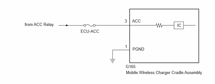
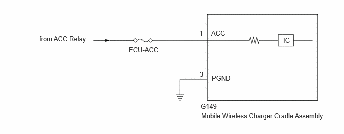
This is the power source circuit for the mobile wireless charger cradle assembly.
WIRING DIAGRAM
for GTMC Made, Type A:
4.188,2.135 4.802,2.333
0.615,0.198
10
false
G165
4.198,2.333 6.833,2.552
2.635,0.219
10
false
Mobile Wireless Charger Cradle Assembly
4.417,1.552 5.031,1.75
0.615,0.198
10
false
PGND
4.167,1.469 4.323,1.667
0.156,0.198
10
false
1
4.156,0.615 4.313,0.813
0.156,0.198
10
false
3
4.406,0.615 4.865,0.813
0.458,0.198
10
false
ACC
2.688,0.958 3.417,1.229
0.729,0.271
10
false
ECU-ACC
0.823,0.729 1.896,1
1.073,0.271
10
false
from ACC Relay
5.906,0.76 6.219,0.958
0.313,0.198
10
false
IC
for SFTM Made, Type B:
4.188,2.135 4.802,2.333
0.615,0.198
10
false
G149
4.198,2.333 6.833,2.552
2.635,0.219
10
false
Mobile Wireless Charger Cradle Assembly
4.417,1.552 5.031,1.75
0.615,0.198
10
false
PGND
4.167,1.469 4.323,1.667
0.156,0.198
10
false
3
4.156,0.615 4.313,0.813
0.156,0.198
10
false
1
4.406,0.615 4.865,0.813
0.458,0.198
10
false
ACC
2.688,0.958 3.417,1.229
0.729,0.271
10
false
ECU-ACC
0.823,0.729 1.896,1
1.073,0.271
10
false
from ACC Relay
5.906,0.76 6.219,0.958
0.313,0.198
10
false
IC
CAUTION / NOTICE / HINT
- NOTICE:
-
Inspect the fuses for circuits related to this system before performing the following procedure.
PROCEDURE
1.CHECK VEHICLE SPECIFICATIONS
a.
Check the vehicle specifications.
- Result:
Result Proceed to for GTMC Made, Type A A for SFTM Made, Type B B
A
2.CHECK HARNESS AND CONNECTOR (MOBILE WIRELESS CHARGER CRADLE ASSEMBLY POWER SOURCE)
B
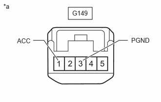
3.CHECK HARNESS AND CONNECTOR (MOBILE WIRELESS CHARGER CRADLE ASSEMBLY POWER SOURCE)
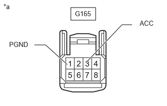
2.CHECK HARNESS AND CONNECTOR (MOBILE WIRELESS CHARGER CRADLE ASSEMBLY POWER SOURCE)
a.
1.458,0.156 1.969,0.417
0.51,0.26
1.385,1.333 0.938,0.927
0.938,0.927 0.708,0.927
true
2.719,0.51 2.51,0.51
2.51,0.51 1.771,1.292
true
0.073,0.052 0.385,0.208
0.313,0.156
10
false
*a
1.542,0.198 2,0.396
0.458,0.198
10
false
G165
0.188,0.833 0.646,1.073
0.458,0.24
10
false
PGND
2.875,0.396 3.26,0.615
0.385,0.219
10
false
ACC
| *a | Front view of wire harness connector
(to Mobile Wireless Charger Cradle Assembly) |
Disconnect the mobile wireless charger cradle assembly connector.
b.
Measure the resistance according to the value(s) in the table below.
- Standard Resistance:
Tester Connection Condition Specified Condition G165-1 (PGND) - Body ground Always Below 1 Ω
c.
Measure the voltage according to the value(s) in the table below.
- Standard Voltage:
Tester Connection Switch Condition Specified Condition G165-3 (ACC) - Body ground Ignition switch ACC 11 to 14 V
- Result:
Proceed to OK NG
OK
PROCEED TO NEXT SUSPECTED AREA SHOWN IN PROBLEM SYMPTOMS TABLE
NG
REPAIR OR REPLACE HARNESS OR CONNECTOR
3.CHECK HARNESS AND CONNECTOR (MOBILE WIRELESS CHARGER CRADLE ASSEMBLY POWER SOURCE)
a.
1.458,0.156 1.969,0.417
0.51,0.26
1.24,1.292 0.938,0.865
0.938,0.865 0.708,0.865
true
2.729,0.865 2.542,0.865
2.542,0.865 1.771,1.292
true
0.073,0.052 0.385,0.208
0.313,0.156
10
false
*a
1.542,0.198 2,0.396
0.458,0.198
10
false
G149
2.802,0.781 3.26,1.021
0.458,0.24
10
false
PGND
0.365,0.792 0.75,1.01
0.385,0.219
10
false
ACC
| *a | Front view of wire harness connector
(to Mobile Wireless Charger Cradle Assembly) |
Disconnect the mobile wireless charger cradle assembly connector.
b.
Measure the resistance according to the value(s) in the table below.
- Standard Resistance:
Tester Connection Condition Specified Condition G149-3 (PGND) - Body ground Always Below 1 Ω
c.
Measure the voltage according to the value(s) in the table below.
- Standard Voltage:
Tester Connection Switch Condition Specified Condition G149-1 (ACC) - Body ground Ignition switch ACC 11 to 14 V
- Result:
Proceed to OK NG
OK
PROCEED TO NEXT SUSPECTED AREA SHOWN IN PROBLEM SYMPTOMS TABLE
NG
REPAIR OR REPLACE HARNESS OR CONNECTOR