EXTERIOR PANELS / TRIM NAME PLATE INSTALLATION
PROCEDURE

 75741E
1.INSTALL SYMBOL EMBLEM (for Type A)
75741E
1.INSTALL SYMBOL EMBLEM (for Type A)
- HINT:
-
When installing the symbol emblem, heat the back door outside garnish sub-assembly and symbol emblem using a heat light.
- Standard:
Item Temperature Back Door Outside Garnish Sub-assembly 20 to 30°C (68 to 86°F) Symbol Emblem 20 to 30°C (68 to 86°F)
- CAUTION:
-
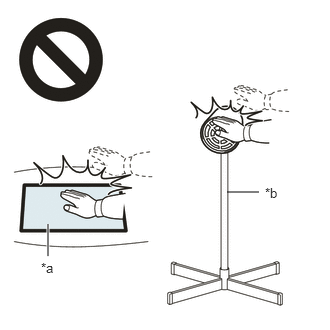 2.365,2 2.698,2 false 0.5,2.333 0.5,2.667 true 0.427,2.708 0.74,2.865 0.313,0.156 10 false *a 2.76,1.927 3.073,2.083 0.313,0.156 10 false *b
*a Heated Part *b Heat Light
- ·
Do not touch the heat light and heated parts.
·Touching the heat light may result in burns.
·Touching heated parts for a long time may result in burns.
- NOTICE:
-
Do not heat the back door outside garnish sub-assembly and symbol emblem excessively.
Clean the surface of the back door outside garnish sub-assembly.
Using a heat light, heat the back door outside garnish sub-assembly surface.
Remove any remaining double-sided tape from the back door outside garnish sub-assembly.
Wipe off any tape adhesive residue with cleaner.
- NOTICE:
- ·
Installing the symbol emblem with any double-sided tape remaining may cause poor adhesion. Perform this procedure until the tape is sufficiently removed.
·Make sure to use a cloth when removing. Using a screwdriver, etc., may cause damage and poor adhesion.
Using a heat light, heat the back door outside garnish sub-assembly and a new symbol emblem.
Remove the release paper from the symbol emblem.
- NOTICE:
-
After removing the peeling paper, do not touch the surface of the tape with your fingers or cotton work gloves.
Align the boss positions and install the symbol emblem.
- NOTICE:
-
The application strength of the symbol emblem will weaken if reapplied. If reapplication is necessary, be sure to replace it with a new one.
- HINT:
-
Apply pressure so that it does not lift up from the back door outside garnish sub-assembly.
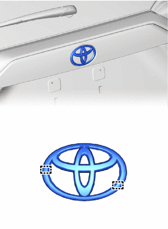
| *a | Boss Position |
for Gasoline Model:
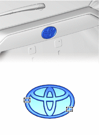
| *a | Boss Position |
for HV Model:
75741E
2.INSTALL SYMBOL EMBLEM (for Type B)
- HINT:
-
When installing the symbol emblem, heat the back door outside garnish sub-assembly and symbol emblem using a heat light.
- Standard:
Item Temperature Back Door Outside Garnish Sub-assembly 20 to 30°C (68 to 86°F) Symbol Emblem 20 to 30°C (68 to 86°F)
- CAUTION:
-
2.365,2 2.698,2 false 0.5,2.333 0.5,2.667 true 0.427,2.708 0.74,2.865 0.313,0.156 10 false *a 2.76,1.927 3.073,2.083 0.313,0.156 10 false *b
*a Heated Part *b Heat Light
- ·
Do not touch the heat light and heated parts.
·Touching the heat light may result in burns.
·Touching heated parts for a long time may result in burns.
- NOTICE:
-
Do not heat the back door outside garnish sub-assembly and symbol emblem excessively.
Clean the surface of the back door outside garnish sub-assembly.
Using a heat light, heat the back door outside garnish sub-assembly surface.
Remove any remaining double-sided tape from the back door outside garnish sub-assembly.
Wipe off any tape adhesive residue with cleaner.
- NOTICE:
- ·
Installing the symbol emblem with any double-sided tape remaining may cause poor adhesion. Perform this procedure until the tape is sufficiently removed.
·Make sure to use a cloth when removing. Using a screwdriver, etc., may cause damage and poor adhesion.
Using a heat light, heat the back door outside garnish sub-assembly and the new symbol emblem.
Remove the release paper from the symbol emblem.
- NOTICE:
-
After removing the peeling paper, do not touch the surface of the tape with your fingers or cotton work gloves.
Align the boss positions and install the symbol emblem.
- NOTICE:
-
The application strength of the symbol emblem will weaken if reapplied. If reapplication is necessary, be sure to replace it with a new one.
- HINT:
-
Apply pressure so that it does not lift up from the back door outside garnish sub-assembly.
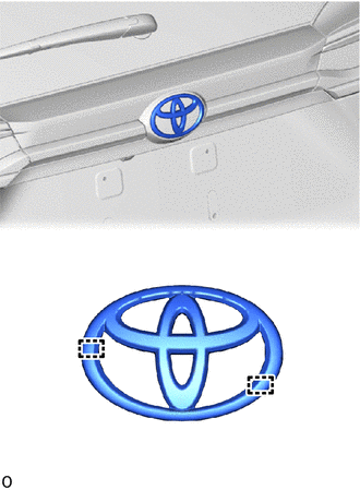
| *a | Boss Position |
for Gasoline Model:
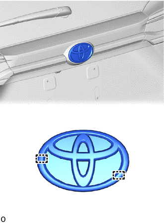
| *a | Boss Position |
for HV Model:
75441E
3.INSTALL BACK DOOR NO. 1 NAME PLATE
- HINT:
-
When installing the back door No. 1 name plate, heat the back door panel and back door No. 1 name plate using a heat light.
- Standard:
Item Temperature Back Door Panel 40 to 60°C (104 to 140°F) Back Door No. 1 Name Plate 20 to 30°C (68 to 86°F)
- CAUTION:
-
2.365,2 2.698,2 false 0.5,2.333 0.5,2.667 true 0.427,2.708 0.74,2.865 0.313,0.156 10 false *a 2.76,1.927 3.073,2.083 0.313,0.156 10 false *b
*a Heated Part *b Heat Light
- ·
Do not touch the heat light and heated parts.
·Touching the heat light may result in burns.
·Touching heated parts for a long time may result in burns.
- NOTICE:
-
Do not heat the back door panel and back door No. 1 name plate excessively.
Clean the surface of the back door panel.
Using a heat light, heat the back door panel surface.
Remove any remaining double-sided tape from the back door panel.
Wipe off any tape adhesive residue with cleaner.
- NOTICE:
- ·
Installing the back door No. 1 name plate with any double-sided tape remaining may cause poor adhesion. Perform this procedure until the tape is sufficiently removed.
·Make sure to use a cloth when removing. Using a screwdriver, etc., may cause damage and poor adhesion.
Using a heat light, heat the back door panel and the new back door No. 1 name plate.
Remove the release paper from the back door No. 1 name plate.
- NOTICE:
-
After removing the peeling paper, do not touch the surface of the tape with your fingers or cotton work gloves.
Install the back door No. 1 name plate as shown in the illustration.
- NOTICE:
-
The application strength of the back door No. 1 name plate will weaken if reapplied. If reapplication is necessary, be sure to replace it with a new one.
- HINT:
-
Apply pressure so that it does not lift up from the back door panel.
for Type A:
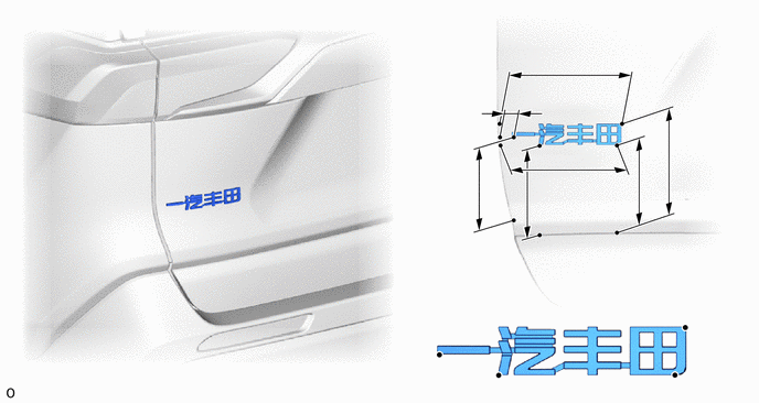
| *a | Reference Values | *b | Back Door Edge Line |
| *c | Back Door Lower Outside Garnish Sub-assembly Upper Side Edge | - | - |
- Standard Measurement:
Area Measurement Area Measurement A 170.7 mm (6.72 in.) B 164.5 mm (6.48 in.) C 115.2 mm (4.54 in.) D 20.1 mm (0.791 in.) E 120.8 mm (4.76 in.) F 118.7 mm (4.67 in.) G 147.9 mm (5.82 in.) - -
for Type B:
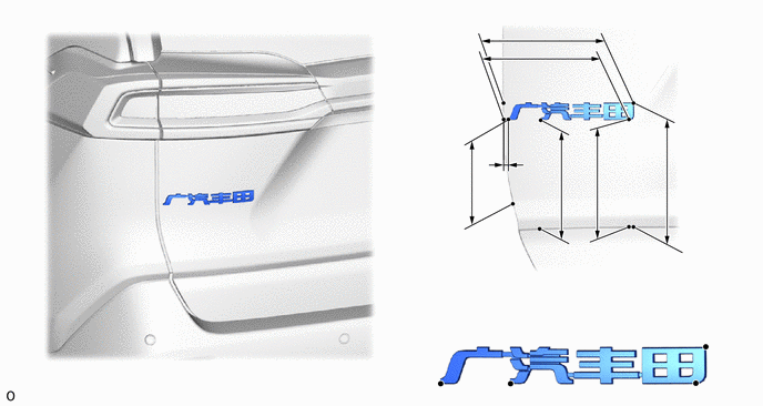
| *a | Reference Values | *b | Back Door Edge Line |
| *c | Back Door Lower Outside Garnish Sub-assembly Upper Side Edge | - | - |
- Standard Measurement:
Area Measurement Area Measurement A 193.9 mm (7.63 in.) B 185.9 mm (7.32 in.) C 93.7 mm (3.69 in.) D 8.6 mm (0.34 in.) E 164.6 mm (6.48 in.) F 158 mm (6.22 in.) G 183.2 mm (7.21 in.) - -
75445A
4.INSTALL BACK DOOR NO. 5 NAME PLATE
- HINT:
-
When installing the back door No. 5 name plate, heat the back door panel and back door No. 5 name plate using a heat light.
- Standard:
Item Temperature Back Door Panel 40 to 60°C (104 to 140°F) Back Door No. 5 Name Plate 20 to 30°C (68 to 86°F)
- CAUTION:
-
2.365,2 2.698,2 false 0.5,2.333 0.5,2.667 true 0.427,2.708 0.74,2.865 0.313,0.156 10 false *a 2.76,1.927 3.073,2.083 0.313,0.156 10 false *b
*a Heated Part *b Heat Light
- ·
Do not touch the heat light and heated parts.
·Touching the heat light may result in burns.
·Touching heated parts for a long time may result in burns.
- NOTICE:
-
Do not heat the back door panel and back door No. 5 name plate excessively.
Clean the surface of the back door panel.
Using a heat light, heat the back door panel surface.
Remove any remaining double-sided tape from the back door panel.
Wipe off any tape adhesive residue with cleaner.
- NOTICE:
- ·
Installing the back door No. 5 name plate with any double-sided tape remaining may cause poor adhesion. Perform this procedure until the tape is sufficiently removed.
·Make sure to use a cloth when removing. Using a screwdriver, etc., may cause damage and poor adhesion.
Using a heat light, heat the back door panel and the new back door No. 5 name plate.
Remove the release paper from the back door No. 5 name plate.
- NOTICE:
-
After removing the peeling paper, do not touch the surface of the tape with your fingers or cotton work gloves.
Install the back door No. 5 name plate as shown in the illustration.
- NOTICE:
-
The application strength of the back door No. 5 name plate will weaken if reapplied. If reapplication is necessary, be sure to replace it with a new one.
- HINT:
-
Apply pressure so that it does not lift up from the back door panel.
for Type A:
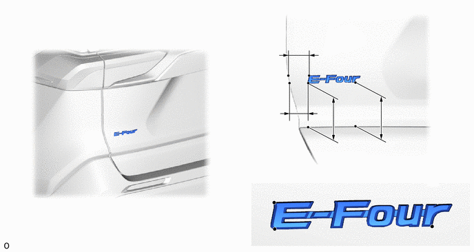
| *a | Reference Values | *b | Back Door Edge Line |
| *c | Back Door Lower Outside Garnish Sub-assembly Upper Side Edge | - | - |
- Standard Measurement:
Area Measurement Area Measurement A 36.3 mm (1.43 in.) B 93.4 mm (3.68 in.) C 91.8 mm (3.61 in.) D 30.5 mm (1.20 in.)
for Type B:
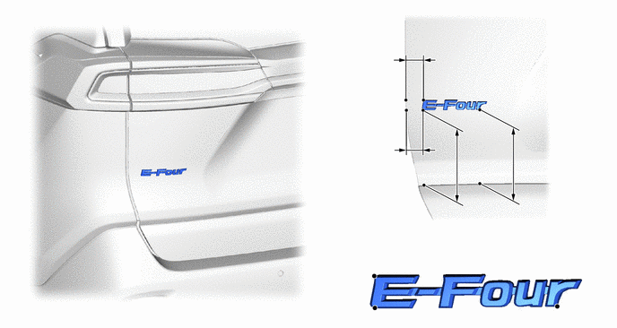
| *a | Reference Values | *b | Back Door Edge Line |
| *c | Back Door Lower Outside Garnish Sub-assembly Upper Side Edge | - | - |
- Standard Measurement:
Area Measurement Area Measurement A 31.1 mm (1.22 in.) B 132 mm (5.20 in.) C 129.3 mm (5.09 in.) D 28.8 mm (1.13 in.)
75443
5.INSTALL BACK DOOR NO. 3 NAME PLATE
- HINT:
-
When installing the back door No. 3 name plate, heat the back door panel and back door No. 3 name plate using a heat light.
- Standard:
Item Temperature Back Door Panel 40 to 60°C (104 to 140°F) Back Door No. 3 Name Plate 20 to 30°C (68 to 86°F)
- CAUTION:
-
2.365,2 2.698,2 false 0.5,2.333 0.5,2.667 true 0.427,2.708 0.74,2.865 0.313,0.156 10 false *a 2.76,1.927 3.073,2.083 0.313,0.156 10 false *b
*a Heated Part *b Heat Light
- ·
Do not touch the heat light and heated parts.
·Touching the heat light may result in burns.
·Touching heated parts for a long time may result in burns.
- NOTICE:
-
Do not heat the back door panel and back door No. 3 name plate excessively.
Clean the surface of the back door panel.
Using a heat light, heat the back door panel surface.
Remove any remaining double-sided tape from the back door panel.
Wipe off any tape adhesive residue with cleaner.
- NOTICE:
- ·
Installing the back door No. 3 name plate with any double-sided tape remaining may cause poor adhesion. Perform this procedure until the tape is sufficiently removed.
·Make sure to use a cloth when removing. Using a screwdriver, etc., may cause damage and poor adhesion.
Using a heat light, heat the back door panel and the new back door No. 3 name plate.
Remove the release paper from the back door No. 3 name plate.
- NOTICE:
-
After removing the peeling paper, do not touch the surface of the tape with your fingers or cotton work gloves.
Install the back door No. 3 name plate as shown in the illustration.
- NOTICE:
-
The application strength of the back door No. 3 name plate will weaken if reapplied. If reapplication is necessary, be sure to replace it with a new one.
- HINT:
-
Apply pressure so that it does not lift up from the back door panel.
for Type A:
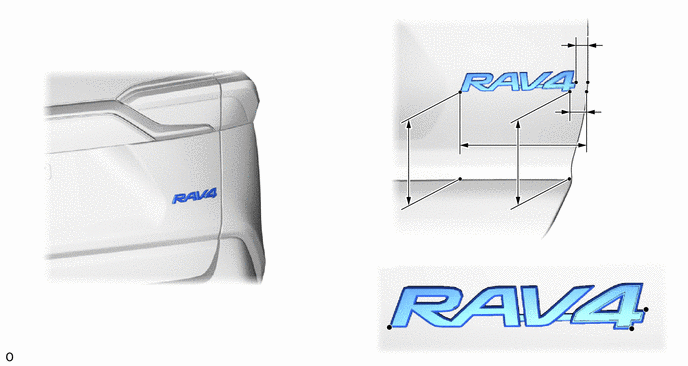
| *a | Reference Values | *b | Back Door Edge Line |
| *c | Back Door Lower Outside Garnish Sub-assembly Upper Side Edge | - | - |
- Standard Measurement:
Area Measurement Area Measurement A 16.7 mm (0.657 in.) B 24.1 mm (0.949 in.) C 172.6 mm (6.80 in.) D 122.7 mm (4.83 in.) E 120.7 mm (4.75 in.) - -
for Type B:
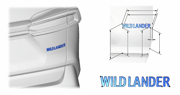
| *a | Reference Values | *b | Back Door Edge Line |
| *c | Back Door Lower Outside Garnish Sub-assembly Upper Side Edge | - | - |
- Standard Measurement:
Area Measurement Area Measurement A 189.2 mm (7.45 in.) B 185 mm (7.28 in.) C 117 mm (4.61 in.) D 13.2 mm (0.520 in.) E 165.8 mm (6.53 in.) F 158.3 mm (6.23 in.) G 183.9 mm (7.24 in.) - -
75444A
6.INSTALL BACK DOOR NO. 4 NAME PLATE
- HINT:
-
When installing the back door No. 4 name plate, heat the back door panel and back door No. 4 name plate using a heat light.
- Standard:
Item Temperature Back Door Panel 40 to 60°C (104 to 140°F) Back Door No. 4 Name Plate 20 to 30°C (68 to 86°F)
- CAUTION:
-
2.365,2 2.698,2 false 0.5,2.333 0.5,2.667 true 0.427,2.708 0.74,2.865 0.313,0.156 10 false *a 2.76,1.927 3.073,2.083 0.313,0.156 10 false *b
*a Heated Part *b Heat Light
- ·
Do not touch the heat light and heated parts.
·Touching the heat light may result in burns.
·Touching heated parts for a long time may result in burns.
- NOTICE:
-
Do not heat the back door panel and back door No. 4 name plate excessively.
Clean the surface of the back door panel.
Using a heat light, heat the back door panel surface.
Remove any remaining double-sided tape from the back door panel.
Wipe off any tape adhesive residue with cleaner.
- NOTICE:
- ·
Installing the back door No. 4 name plate with any double-sided tape remaining may cause poor adhesion. Perform this procedure until the tape is sufficiently removed.
·Make sure to use a cloth when removing. Using a screwdriver, etc., may cause damage and poor adhesion.
Using a heat light, heat the back door panel and the new back door No. 4 name plate.
Remove the release paper from the back door No. 4 name plate.
- NOTICE:
-
After removing the peeling paper, do not touch the surface of the tape with your fingers or cotton work gloves.
Install the back door No. 4 name plate as shown in the illustration.
- NOTICE:
-
The application strength of the back door No. 4 name plate will weaken if reapplied. If reapplication is necessary, be sure to replace it with a new one.
- HINT:
-
Apply pressure so that it does not lift up from the back door panel.
for Type A:
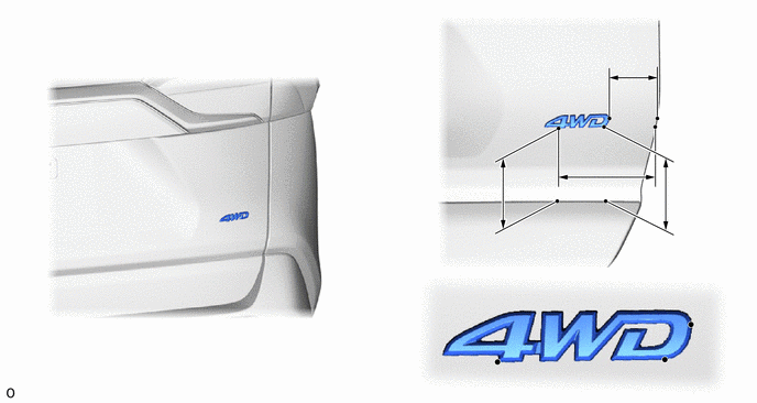
| *a | Reference Values | *b | Back Door Edge Line |
| *c | Back Door Lower Outside Garnish Sub-assembly Upper Side Edge | - | - |
- Standard Measurement:
Area Measurement Area Measurement A 58.8 mm (2.31 in.) B 119 mm (4.69 in.) C 93.6 mm (3.69 in.) D 91.2 mm (3.59 in.)
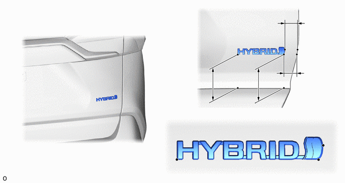
| *a | Reference Values | *b | Back Door Edge Line |
| *c | Back Door Lower Outside Garnish Sub-assembly Upper Side Edge | - | - |
- Standard Measurement:
Area Measurement Area Measurement A 33.8 mm (1.33 in.) B 37.1 mm (1.46 in.) C 92.9 mm (3.66 in.) D 91.5 mm (3.60 in.)
for Type B:
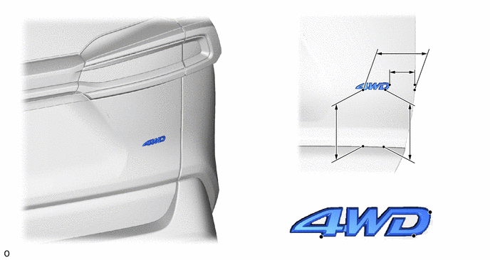
| *a | Reference Values | *b | Back Door Edge Line |
| *c | Back Door Lower Outside Garnish Sub-assembly Upper Side Edge | - | - |
- Standard Measurement:
Area Measurement Area Measurement A 117.5 mm (4.63 in.) B 58 mm (2.28 in.) C 129.7 mm (5.11 in.) D 128.1 mm (5.04 in.)
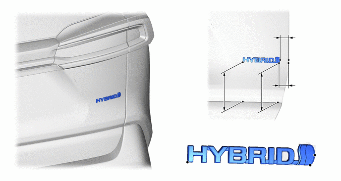
| *a | Reference Values | *b | Back Door Edge Line |
| *c | Back Door Lower Outside Garnish Sub-assembly Upper Side Edge | - | - |
- Standard Measurement:
Area Measurement Area Measurement A 28.6 mm (1.13 in.) B 33 mm (1.30 in.) C 129.1 mm (5.08 in.) D 129.3 mm (5.09 in.)
75362
7.INSTALL FRONT FENDER NO. 2 NAME PLATE
- HINT:
-
When installing the front fender No. 2 name plate, heat the fender panel and front fender No. 2 name plate using a heat light.
- Standard:
Item Temperature Fender Panel 40 to 60°C (104 to 140°F) Front Fender No. 2 Name Plate 20 to 30°C (68 to 86°F)
- CAUTION:
-
2.365,2 2.698,2 false 0.5,2.333 0.5,2.667 true 0.427,2.708 0.74,2.865 0.313,0.156 10 false *a 2.76,1.927 3.073,2.083 0.313,0.156 10 false *b
*a Heated Part *b Heat Light
- ·
Do not touch the heat light and heated parts.
·Touching the heat light may result in burns.
·Touching heated parts for a long time may result in burns.
- NOTICE:
-
Do not heat the fender panel and front fender No. 2 name plate excessively.
Clean the surface of the fender panel.
Using a heat light, heat the fender panel surface.
Remove any remaining double-sided tape from the fender panel.
Wipe off any tape adhesive residue with cleaner.
- NOTICE:
- ·
Installing the front fender No. 2 name plate with any double-sided tape remaining may cause poor adhesion. Perform this procedure until the tape is sufficiently removed.
·Make sure to use a cloth when removing. Using a screwdriver, etc., may cause damage and poor adhesion.
Using a heat light, heat the fender panel and the new front fender No. 2 name plate.
Remove the release paper from the front fender No. 2 name plate.
- NOTICE:
-
After removing the peeling paper, do not touch the surface of the tape with your fingers or cotton work gloves.
Install the front fender No. 2 name plate as shown in the illustration.
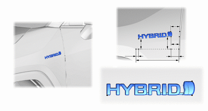
| *a | Reference Values | *b | Lower Side Baseline |
| *c | Front Fender Edge Line | - | - |
- Standard Measurement:
Area Measurement Area Measurement A 200 mm (7.87 in.) B 18.5 mm (0.726 in.) C 35.2 mm (1.39 in.) D 43.2 mm (1.70 in.) E 56.8 mm (2.23 in.) F 37.4 mm (1.47 in.) G 41.2 mm (1.62 in.) - -
- NOTICE:
-
The application strength of the front fender No. 2 name plate will weaken if reapplied. If reapplication is necessary, be sure to replace it with a new one.
- HINT:
-
Apply pressure so that it does not lift up from the fender panel.
75361A
8.INSTALL FRONT FENDER NO. 1 NAME PLATE
- HINT:
-
When installing the front fender No. 1 name plate, heat the fender panel and front fender No. 1 name plate using a heat light.
- Standard:
Item Temperature Fender Panel 40 to 60°C (104 to 140°F) Front Fender No. 1 Name Plate 20 to 30°C (68 to 86°F)
- CAUTION:
-
2.365,2 2.698,2 false 0.5,2.333 0.5,2.667 true 0.427,2.708 0.74,2.865 0.313,0.156 10 false *a 2.76,1.927 3.073,2.083 0.313,0.156 10 false *b
*a Heated Part *b Heat Light
- ·
Do not touch the heat light and heated parts.
·Touching the heat light may result in burns.
·Touching heated parts for a long time may result in burns.
- NOTICE:
-
Do not heat the fender panel and front fender No. 1 name plate excessively.
Clean the surface of the fender panel.
Using a heat light, heat the fender panel surface.
Remove any remaining double-sided tape from the fender panel.
Wipe off any tape adhesive residue with cleaner.
- NOTICE:
- ·
Installing the front fender No. 1 name plate with any double-sided tape remaining may cause poor adhesion. Perform this procedure until the tape is sufficiently removed.
·Make sure to use a cloth when removing. Using a screwdriver, etc., may cause damage and poor adhesion.
Using a heat light, heat the fender panel and the new front fender No. 1 name plate.
Remove the release paper from the front fender No. 1 name plate.
- NOTICE:
-
After removing the peeling paper, do not touch the surface of the tape with your fingers or cotton work gloves.
Install the front fender No. 1 name plate as shown in the illustration.
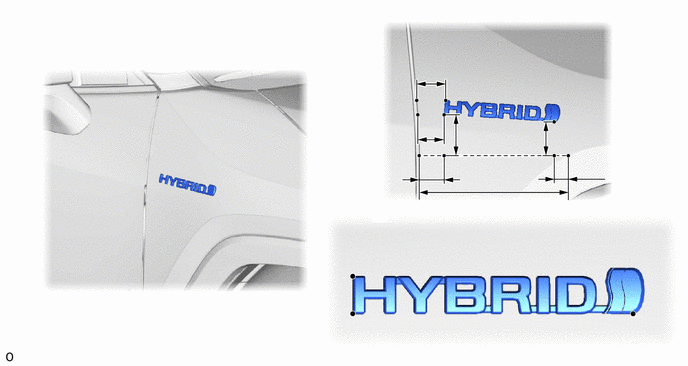
| *a | Reference Values | *b | Lower Side Baseline |
| *c | Front Fender Edge Line | - | - |
- Standard Measurement:
Area Measurement Area Measurement A 200 mm (7.87 in.) B 20.7 mm (0.815 in.) C 32.7 mm (1.29 in.) D 43.5 mm (1.71 in.) E 57.9 mm (2.28 in.) F 34.9 mm (1.37 in.) G 38.0 mm (1.50 in.) - -
- NOTICE:
-
The application strength of the front fender No. 1 name plate will weaken if reapplied. If reapplication is necessary, be sure to replace it with a new one.
- HINT:
-
Apply pressure so that it does not lift up from the fender panel.