THEFT DETERRENT / KEYLESS ENTRY DIGITAL KEY SYSTEM TERMINALS OF ECU
- HINT:
-
Make sure to cancel power saving mode when measuring the standard values.
CERTIFICATION ECU (SMART KEY ECU ASSEMBLY)
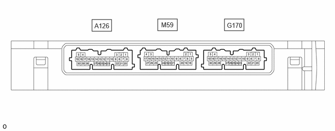
Disconnect the A126 and G170 certification ECU (smart key ECU assembly) connectors.
Measure the voltage and resistance according to the value(s) in the table below.
| Tester Connection | Terminal Description | Condition | Specified Condition |
|---|---|---|---|
| G170-6 (+B) - G170-29 (E) | Power source | Ignition switch off | 11 to 14 V |
| A126-22 (CUTB) - Body ground | Dark current cut pin* | Ignition switch off | 11 to 14 V |
| G170-29 (E) - Body ground | GND | Always | Below 1 Ω |
*: In order to prevent the vehicle auxiliary battery from being depleted when the vehicle is shipped long distances, a fuse that cuts unnecessary electrical load while the vehicle is being shipped is installed in the circuit. If the fuse is removed, the circuit becomes open. If the fuse that is between the vehicle auxiliary battery and terminal CUTB is removed and the circuit is open, the certification ECU (smart key ECU assembly) changes to a certain control mode (example: the transmission of radio waves every 0.25 seconds, which form the detection area, stops).
Connect the A126 and G170 certification ECU (smart key ECU assembly) connectors.
Measure the voltage according to the value(s) in the table below.
| Tester Connection | Terminal Description | Condition | Specified Condition |
|---|---|---|---|
| G170-17 (UAT2) - G170-29 (E) | UART communication line | All of the following conditions are met:
·
Ignition switch off ·
Door lock/unlock operation has been not performed via digital key ·
Digital key is not being operated |
11 to 14 V |
DIGITAL KEY ECU ASSEMBLY

Disconnect the N68 Digital key ECU assembly connector.
Measure the voltage and resistance according to the value(s) in the table below.
| Tester Connection | Terminal Description | Condition | Specified Condition |
|---|---|---|---|
| N68-1 (+B) - N68-10 (GND) | Power source | Ignition switch off | 11 to 14 V |
| N68-10 (GND) - Body ground | GND | Always | Below 1 Ω |
Connect the N68 Digital key ECU assembly connector.
Measure the voltage and check for pulses according to the value(s) in the table below.
| Tester Connection | Terminal Description | Condition | Specified Condition |
|---|---|---|---|
| N68-4 (PWI1) - N68-10 (GND) | BLE digital key receiver power source | Digital key is in BLE connection range. | 8.5 to 14 V |
| N68-12 (PWO1) - N68-10 (GND) | BLE digital key receiver power source | Digital key is in BLE connection range. | 8.5 to 14 V |
| N68-14 (LIN1) - N68-10 (GND) | LIN communication line | Digital key is in driver door digital key detection range. | Pulse generation |
| N68-15 (LIN2) - N68-10 (GND) | LIN communication line | Digital key is in front passenger door digital key detection range. | Pulse generation |
| N68-20 (LIN3) - N68-10 (GND) | LIN communication line | Digital key is in back door digital key detection range. | Pulse generation |
| N68-21 (LIN4) - N68-10 (GND) | LIN communication line | Digital key is in in-vehicle operating range . | Pulse generation |
| N68-23 (UART) - N68-10 (GND) | UART communication line | All of the following conditions are met:
·
Ignition switch off ·
Door lock/unlock operation has been not performed via digital key → performed |
Pulse generation
(See waveform) |
Using an oscilloscope, check the waveform of the ECU.
- NOTICE:
-
The oscilloscope waveform shown in the illustration is an example for reference only. Noise, chattering, etc. are not shown.
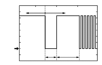
| *a | Before door lock/unlock operation using digital key |
| *b | After door lock/unlock operation using digital key |
| *c | Approximately 15 ms. |
| *d | 15 to 50 ms. |
Waveform
| Item | Content |
|---|---|
| Tester Connection | N68-23 (UART) - N68-10 (GND) |
| Tool Setting | 2 V/DIV., 20 ms./DIV. |
| Condition | All of the following conditions are met:
·
Ignition switch off ·
Door lock/unlock operation has been not performed via digital key → performed |