INTERIOR PANELS / TRIM FRONT CONSOLE BOX REASSEMBLY
PROCEDURE

 85535B
1.INSTALL NO. 1 POWER OUTLET SOCKET COVER
85535B
1.INSTALL NO. 1 POWER OUTLET SOCKET COVER
85530
2.INSTALL NO. 1 POWER OUTLET SOCKET ASSEMBLY
58808
3.INSTALL SHIFTING HOLE COVER SUB-ASSEMBLY

Attach the claw and guide to install the shifting hole cover sub-assembly.
84010D
4.INSTALL INTEGRATION CONTROL AND PANEL ASSEMBLY
35978
5.INSTALL SHIFT POSITION INDICATOR
58911A
6.INSTALL NO. 1 BOX SIDE PANEL
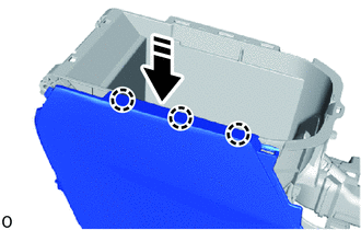

|
Install in this Direction |
Attach the claw in direction indicated by the arrow shown in the illustration.
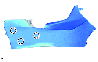
Attach the claw to install the No. 1 box panel.
58985
7.INSTALL CONSOLE BOX RETAINER
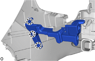
Attach the claw to install the console box retainer.
58912C
8.INSTALL NO. 2 BOX SIDE PANEL
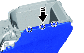
|
|
Install in this Direction |
Attach the claw in direction indicated by the arrow shown in the illustration.
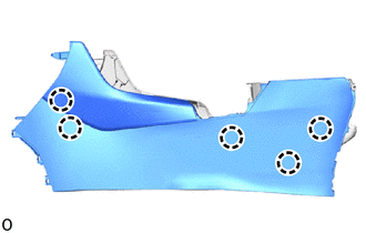
Attach the claw to install the No. 2 box panel.
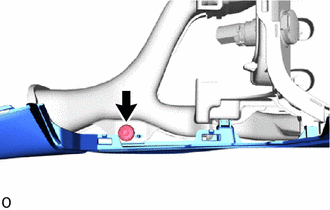
Attach the clip.
58920A
9.INSTALL REAR CONSOLE ARMREST ASSEMBLY
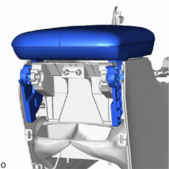
Install the rear console armrest assembly.
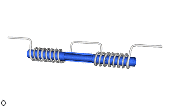
Install the console box spacer into the console box mounting bracket spring.
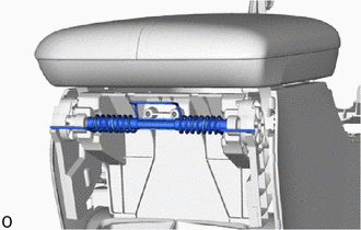
Set the console box spacer and console box mounting bracket spring.
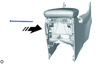
|
|
Install in this Direction |
Insert in the direction of the arrow shown in the illustration to install the console compartment door stopper pin.
- HINT:
-
The console compartment door stopper pin can be inserted from either the right or left sides.
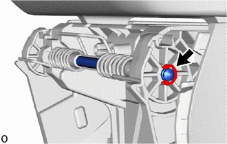
Install a new E-ring.
- HINT:
-
When installing, reinstallation is not required.
Open the rear console armrest assembly.
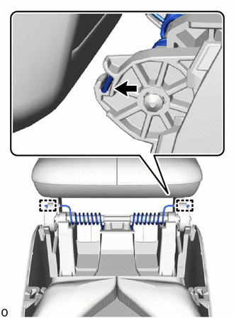
Attach the guide to install the console box mounting bracket spring both side.
Close the rear console armrest assembly.