K121F CVT CONTINUOUSLY VARIABLE TRANSAXLE SYSTEM P084011 Transmission Fluid Pressure Sensor/Switch "A" Circuit Short To Ground
DESCRIPTION
The ECM performs learning control for the belt clamping pressure based on the belt clamping pressure signal, which is output by the oil pressure sensor.
| DTC No. | Detection Item | DTC Detection Condition | Trouble Area | MIL | DTC Output from | Priority | Note |
|---|---|---|---|---|---|---|---|
| P084011 | Transmission Fluid Pressure Sensor/Switch "A" Circuit Short To Ground | When 2 seconds or more have elapsed since engine start, a short to ground is detected in the oil pressure sensor circuit for 0.5 seconds or more (1-trip detection logic). | ·
Wire harness or connector ·
Oil pressure sensor ·
ECM |
Comes on | Engine | A | SAE Code:
P0842 |
MONITOR DESCRIPTION
This DTC indicates a short to ground in the oil pressure sensor circuit. If there is a short to ground in the oil pressure sensor circuit, the ECM detects the malfunction, illuminates the MIL and stores a DTC.
CONFIRMATION DRIVING PATTERN
- HINT:
- ·
After repairs have been completed, clear the DTCs and then check that the vehicle has returned to normal by performing the following All Readiness check procedure.
·When clearing the permanent DTCs, refer to the Clear Permanent DTC procedure.
Clear the DTCs (even if no DTCs are stored, perform the clear DTC procedure).
Turn the ignition switch off and wait for 2 minutes or more.
Start the engine and wait for 5 seconds or more. [*1]
- HINT:
-
[*1]: Normal judgment procedure.
-
The normal judgment procedure is used to complete DTC judgment and also used when clearing permanent DTCs.
Enter the following menus: Powertrain / Engine / Utility / All Readiness.
Input the DTC: P084011.
Check the DTC judgment result.
| GTS Display | Description |
|---|---|
| NORMAL | ·
DTC judgment completed ·
System normal |
| ABNORMAL | ·
DTC judgment completed ·
System abnormal |
| INCOMPLETE | ·
DTC judgment not completed ·
Perform driving pattern after confirming DTC enabling conditions |
| N/A | ·
Unable to perform DTC judgment ·
Number of DTCs which do not fulfill DTC preconditions has reached ECU memory limit |
- HINT:
- ·
If the judgment result shows NORMAL, the system is normal.
·If the judgment result shows ABNORMAL, the system has a malfunction.
·If the judgment result shows INCOMPLETE or N/A, perform the normal judgment procedure again.
WIRING DIAGRAM
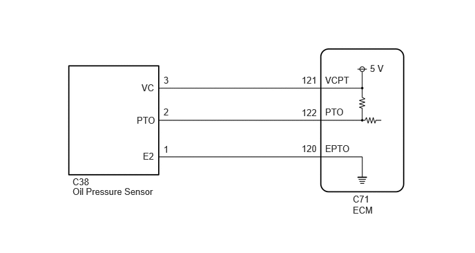
CAUTION / NOTICE / HINT
- CAUTION:
- ·
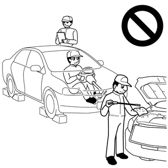
Do not perform a stall test if there are any people or objects near the vehicle.
·The vehicle could begin moving suddenly, resulting in a serious accident.
- ·
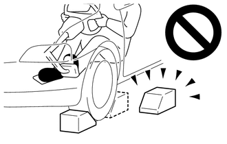
Do not perform a stall test if any wheel chock is out of position.
·The vehicle could begin moving suddenly, resulting in a serious accident.
- ·

Do not perform the stall test on a slippery or low-friction surface that could allow the tires to spin.
·The vehicle could begin moving suddenly, resulting in a serious accident.
- NOTICE:
- ·
Perform the universal trip to clear permanent DTCs.
·Perform registration and/or initialization when parts related to the continuously variable transaxle system are replaced.
·Check that no DTCs are stored after performing initialization.
PROCEDURE
- CAUTION:
-
A stall speed test should always be performed with at least 2 people. One person should observe the condition of the wheels and wheel chocks while the other is performing the test.
- NOTICE:
- ·
This test must be performed after checking and confirming that the engine is normal.
·Perform this test with the CVT fluid temperature between 50 and 100°C (122 and 212°F).
·Perform this test with the air conditioning off.
·Do not perform the stall speed test for longer than 5 seconds.
·When performing the stall speed test repeatedly, wait for 15 seconds or more between tests.
·Perform this test with the AUTO function (shift-linked function) of the electric parking brake system off.
Pre-procedure1
Warm up the engine.
Fully apply the parking brake and chock all 4 wheels.
- HINT:
-
When the parking brake indicator (red) is illuminated after the electric parking brake switch (integration control and panel assembly) has been pulled to the lock side, the maximum amount of braking force is applied if the electric parking brake switch (integration control and panel assembly) is pulled to the lock side one more time.
Procedure1
According to the display on the GTS, perform the Active Test.
- Powertrain > Engine > Active Test
-
Tester Display Measurement Item Control Range Diagnostic Note Activate the TC Terminal Turn on and off TC and TE1 (CG) connection ON or OFF ·ON: TC and TE1 are connected.
·OFF: TC and TE1 are disconnected.
(Vehicle Condition)Ignition switch ON, engine stopped and shift lever in P
According to the display on the GTS, read the Data List.
- Powertrain > Engine > Data List
-
Tester Display Measurement Item Range Normal Condition Diagnostic Note Belt Clamping Force Sensor Secondary oil pressure value Min.: -64 MPa
Max.: 63.998 MPaSecondary oil pressure inspection:
3.0 to 7.0 MPa (30.6 to 71.4 kgf/cm2, 435 to 1015 psi): D position stall test-
- Powertrain > Engine > Active Test
-
Active Test Display Activate the TC Terminal -
Data List Display Belt Clamping Force Sensor - 50004 372 22 367
- Result:
Result Proceed to The value of Belt Clamping Force Sensor is 3.0 MPa or more, and 7.0 MPa or less A The value of Belt Clamping Force Sensor is more than 7.0 MPa, or less than 3.0 MPa B
- HINT:
- ·
3.0 MPa = 30.6 kgf/cm2, 435 psi
·7.0 MPa = 71.4 kgf/cm2, 1015 psi
Post-procedure1
None
A
B
- HINT:
-
for M20C-FKS:
-
for M20D-FKS:
- Result:
Proceed to NEXT
NEXT
for Registration: Click hereDrivetrain>K121F (CVT)>CONTINUOUSLY VARIABLE TRANSAXLE SYSTEM>REGISTRATION202304,999999,_52,_138817,_0596468,RM100000002AWR8,
for Initialization: Click hereDrivetrain>K121F (CVT)>CONTINUOUSLY VARIABLE TRANSAXLE SYSTEM>INITIALIZATION202304,202405,_52,_138817,_0596468,RM100000002AWR9,202405,202409,_52,_138817,_0596468,RM100000002JJ5Q,202409,999999,_52,_138817,_0596468,RM100000002NRBH,
Pre-procedure1
Disconnect the C38 oil pressure sensor connector.
Turn the ignition switch to ON.
Procedure1
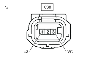
| *a | Front view of wire harness connector (to Oil Pressure Sensor) |
Measure the voltage according to the value(s) in the table below.
- Standard Voltage:
Tester Connection Condition Specified Condition C38-3 (VC) - C38-1 (E2) Ignition switch ON 4.75 to 5.25 V
- Result:
Proceed to OK NG
Post-procedure1
Turn the ignition switch off.
Connect the C38 oil pressure sensor connector.
OK
NG
Pre-procedure1
Disconnect the C38 oil pressure sensor connector.
Disconnect the C71 ECM connector.
Procedure1
Measure the resistance according to the value(s) in the table below.
- Standard Resistance:
Tester Connection Condition Specified Condition C38-2 (PTO) - C71-122 (PTO) Always Below 1 Ω C38-2 (PTO) or C71-122 (PTO) - Body ground and other terminals Always 10 kΩ or higher
- Result:
Proceed to OK NG
Post-procedure1
Connect the C71 ECM connector.
Connect the C38 oil pressure sensor connector.
OK
NG
- HINT:
- Result:
Proceed to NEXT
NEXT
Clear the DTCs.
- Powertrain > Engine > Clear DTCs
- 50002 372
- Result:
Proceed to NEXT
NEXT
- Result:
Proceed to NEXT
NEXT
Read the DTCs.
- Powertrain > Engine > Trouble Codes
- 50001 372
- Result:
Result Proceed to DTCs are not output A P084011 is output B
A
B
- HINT:
-
for M20C-FKS:
-
for M20D-FKS:
- Result:
Proceed to NEXT
NEXT
for Registration: Click hereDrivetrain>K121F (CVT)>CONTINUOUSLY VARIABLE TRANSAXLE SYSTEM>REGISTRATION202304,999999,_52,_138817,_0596468,RM100000002AWR8,
for Initialization: Click hereDrivetrain>K121F (CVT)>CONTINUOUSLY VARIABLE TRANSAXLE SYSTEM>INITIALIZATION202304,202405,_52,_138817,_0596468,RM100000002AWR9,202405,202409,_52,_138817,_0596468,RM100000002JJ5Q,202409,999999,_52,_138817,_0596468,RM100000002NRBH,
Pre-procedure1
Disconnect the C38 oil pressure sensor connector.
Disconnect the C71 ECM connector.
Procedure1
Measure the resistance according to the value(s) in the table below.
- Standard Resistance:
Tester Connection Condition Specified Condition C38-3 (VC) - C71-121 (VCPT) Always Below 1 Ω C38-1 (E2) - C71-120 (EPTO) Always Below 1 Ω C38-3 (VC) or C71-121 (VCPT) - Body ground and other terminals Always 10 kΩ or higher C38-1 (E2) or C71-120 (EPTO) - Body ground and other terminals Always 10 kΩ or higher
- Result:
Proceed to OK NG
Post-procedure1
Connect the C71 ECM connector.
Connect the C38 oil pressure sensor connector.
OK
NG
- HINT:
-
for M20C-FKS:
-
for M20D-FKS:
- Result:
Proceed to NEXT
NEXT
for Registration: Click hereDrivetrain>K121F (CVT)>CONTINUOUSLY VARIABLE TRANSAXLE SYSTEM>REGISTRATION202304,999999,_52,_138817,_0596468,RM100000002AWR8,
for Initialization: Click hereDrivetrain>K121F (CVT)>CONTINUOUSLY VARIABLE TRANSAXLE SYSTEM>INITIALIZATION202304,202405,_52,_138817,_0596468,RM100000002AWR9,202405,202409,_52,_138817,_0596468,RM100000002JJ5Q,202409,999999,_52,_138817,_0596468,RM100000002NRBH,