REAR SUSPENSION REAR SUSPENSION MEMBER(for 2WD) REMOVAL
CAUTION / NOTICE / HINT
The necessary procedures (adjustment, calibration, initialization, or registration) that must be performed after parts are removed and installed, or replaced during rear suspension member sub-assembly removal/installation are shown below.
| Replaced Part or Performed Procedure | Necessary Procedure | Effect/Inoperative Function when Necessary Procedure not Performed | Link |
|---|---|---|---|
| Rear wheel alignment adjustment | 1.
Perform "Reset Memory" 2.
Perform "Calibration" |
·
DTCs are stored ·
ABS warning light illuminates ·
Brake warning light / yellow (minor malfunction) illuminates ·
Slip indicator light illuminates ·
VSC disabled or malfunctions |
( 202304,999999,_54,_083077,_0401811,RM1000000029TH7,) 202304,999999,_54,_083077,_0401811,RM1000000029TH7,)
|
| Suspension, tires, etc. | Parking assist ECU initialization | Panoramic View Monitor System | (202304,999999,_56,_083082,_0586733,RM1000000029R9F,)
|
| Gas leak from exhaust system is repaired | Inspection After Repair | ·
Poor idle, etc. ·
Engine start function, etc. |
for A25B-FXS:
( 202304,202405,_51,_083340,_0402276,RM1000000029D4N,202405,999999,_51,_083340,_0402276,RM100000002JLPS,)
for A25D-FXS: ( 202304,202405,_51,_103786,_0477830,RM100000002AFB3,202405,999999,_51,_103786,_0477830,RM100000002JLPT,)
for A25F-FXS: ( 202304,202409,_51,_105211,_0483212,RM100000002AFCN,202409,999999,_51,_105211,_0483212,RM100000002NSBB,)
|
| Replaced Part or Performed Procedure | Necessary Procedure | Effect/Inoperative Function when Necessary Procedure not Performed | Link |
|---|---|---|---|
| Rear wheel alignment adjustment | 1.
Perform "Reset Memory" 2.
Perform acceleration sensor zero point calibration and store system information memorization |
·
VSC is disabled or malfunctions ·
DTCs are output ·
Slip indicator light illuminates ·
ABS warning light illuminates |
(202304,999999,_54,_083077,_0402316,RM100000002AG8P,)
|
| Suspension, tires, etc. | Parking assist ECU initialization | Panoramic View Monitor System | (202304,999999,_56,_083082,_0586733,RM1000000029R9F,)
|
| Gas leak from exhaust system is repaired | Inspection After Repair | ·
Poor idle, etc. ·
Engine start function, etc. |
for M20C-FKS:
( 202304,202405,_51,_087036,_0418131,RM1000000029CMT,202405,999999,_51,_087036,_0418131,RM100000002IF8T,)
for M20D-FKS: ( 202304,202409,_51,_083058,_0401834,RM1000000029C6V,202409,999999,_51,_083058,_0401834,RM100000002NA8M,)
|
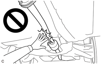
- CAUTION:
-
-
To prevent burns, do not touch the engine, exhaust pipe or other high temperature components while the engine is hot.
PROCEDURE

 1. PRECAUTION (for HV Model)
- NOTICE:
-
After the ignition switch is turned off, there may be a waiting time before disconnecting the negative (-) auxiliary battery terminal.
2.REMOVE REAR WHEEL
17430
3.REMOVE TAIL EXHAUST PIPE ASSEMBLY
58327B
4.REMOVE MAIN MUFFLER HEAT INSULATOR
53896B
5.REMOVE FRONT FENDER FRONT SPLASH SHIELD LH (for Gasoline Model)
53895B
6.REMOVE FRONT FENDER FRONT SPLASH SHIELD RH (for Gasoline Model)
51441
7.REMOVE NO. 1 ENGINE UNDER COVER (for Gasoline Model)
51420
8.REMOVE NO. 2 ENGINE UNDER COVER ASSEMBLY (for Gasoline Model)
58166A
9.REMOVE FRONT FLOOR COVER LH (for Gasoline Model)
58166A
10.REMOVE FRONT FLOOR COVER RH (for Gasoline Model)
58399D
11.REMOVE NO. 2 FLOOR UNDER COVER (for Gasoline Model)
58398F
12.REMOVE NO. 1 FLOOR UNDER COVER (for Gasoline Model)
47319F
13.SEPARATE REAR FLEXIBLE HOSE LH
Remove the bolt and separate the rear flexible hose LH from the rear flexible hose bracket.
47318F
14.SEPARATE REAR FLEXIBLE HOSE RH
- HINT:
-
Perform the same procedure as for the LH side.
48840A
15.REMOVE REAR STABILIZER LINK ASSEMBLY LH
48830D
16.REMOVE REAR STABILIZER LINK ASSEMBLY RH
- HINT:
-
Perform the same procedure as for the LH side.
48812
17.REMOVE REAR STABILIZER BAR
48231B
18.REMOVE REAR COIL SPRING LH
48231A
19.REMOVE REAR COIL SPRING RH
- HINT:
-
Perform the same procedure as for the LH side.
48258C
20.REMOVE REAR LOWER COIL SPRING INSULATOR LH
48258B
21.REMOVE REAR LOWER COIL SPRING INSULATOR RH
- HINT:
-
Perform the same procedure as for the LH side.
48740F
22.REMOVE REAR NO. 2 SUSPENSION ARM ASSEMBLY LH
48730F
23.REMOVE REAR NO. 2 SUSPENSION ARM ASSEMBLY RH
- HINT:
-
Perform the same procedure as for the LH side.
48720A
24.REMOVE REAR NO. 1 SUSPENSION ARM ASSEMBLY LH
48710A
25.REMOVE REAR NO. 1 SUSPENSION ARM ASSEMBLY RH
- HINT:
-
Perform the same procedure as for the LH side.
48790
26.SEPARATE REAR UPPER CONTROL ARM ASSEMBLY LH
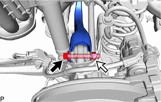
Remove the bolt and nut and separate the rear upper control arm assembly LH from the rear axle carrier sub-assembly LH.
- NOTICE:
-
Because the nut has its own stopper, do not turn the nut. Loosen the bolt with the nut secured.
48770A
27.SEPARATE REAR UPPER CONTROL ARM ASSEMBLY RH
- HINT:
-
Use the same procedure as for the LH side.
51206A
28.REMOVE REAR SUSPENSION MEMBER SUB-ASSEMBLY
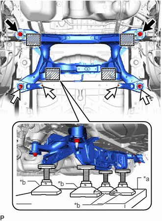
| *a | Engine Lifter |
| *b | Attachment |

|
Attachment and Wooden Block Placement Location |
Using an engine lifter and 4 attachments or equivalent tools, support the rear suspension member sub-assembly as shown in the illustration.
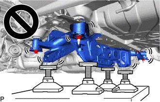
- CAUTION:
-
- ·
The rear suspension member sub-assembly is a very heavy component. Make sure that it is supported securely.
·If the rear suspension member sub-assembly is not securely supported, it may drop, resulting in serious injury.
- NOTICE:
-
Use attachments or equivalent tools to keep the rear suspension member sub-assembly level.
Remove the 2 bolts, 4 nuts, 2 rear suspension member lower stoppers, rear suspension member lower brace LH and rear suspension member lower brace RH.
Slowly lower the rear suspension member sub-assembly.
- NOTICE:
-
When lowering the rear suspension member sub-assembly, be careful not to damage the vehicle body or other components installed to the vehicle.
Remove the 4 rear suspension member cushions from the rear suspension member sub-assembly.
- HINT:
-
Make sure to place an identification mark on the rear suspension member cushion so that they can be reinstalled to their original positions.
48790
29.REMOVE REAR UPPER CONTROL ARM ASSEMBLY LH
48770A
30.REMOVE REAR UPPER CONTROL ARM ASSEMBLY RH
- HINT:
-
Perform the same procedure as for the LH side.
52271E
31.REMOVE REAR SUSPENSION MEMBER FRONT BODY MOUNTING CUSHION (for LH Side)
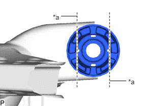
| *a | Bend Portion |
Using a chisel and hammer, bend the 2 portions of the rear suspension member front body mounting cushion rib.
- NOTICE:
-
Make sure to bend the 2 portions of the cushion rib until the claws of SST can fit securely.
Apply lubricant to the contact surfaces of the rear suspension member front body mounting cushion.
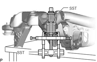
Install SST as shown in the illustration.
- SST
- 09830-10010 (09830-01010, 09830-01040, 09830-01050)
09950-40011 (09951-04010, 09952-04010, 09954-04010, 09955-04061, 09958-04011)
- NOTICE:
-
Apply molybdenum grease to the threads and tip of the SST center bolt before use.
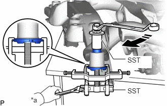
| *a | Hold |

|
Turn |
Using SST, remove the rear suspension member front body mounting cushion while applying lubricant into the clearance between the rear suspension member front body mounting cushion and the rear suspension member sub-assembly.
- SST
- 09830-10010 (09830-01010, 09830-01040, 09830-01050)
09950-40011 (09951-04010, 09952-04010, 09954-04010, 09955-04061, 09958-04011)
- NOTICE:
- ·
Set the claws of SST into the rear suspension member sub-assembly securely as shown in the illustration.
·Tighten SST slowly and evenly.
·Be careful as the rear suspension member front body mounting cushion may fly out.
·The rear suspension member front body mounting cushion cannot be reused.
Remove SST and the rear suspension member front body mounting cushion from the rear suspension member sub-assembly.
52271E
32.REMOVE REAR SUSPENSION MEMBER FRONT BODY MOUNTING CUSHION (for RH Side)
- HINT:
-
Perform the same procedure as for the LH side.
52275A
33.REMOVE REAR SUSPENSION MEMBER REAR BODY MOUNT CUSHION LH
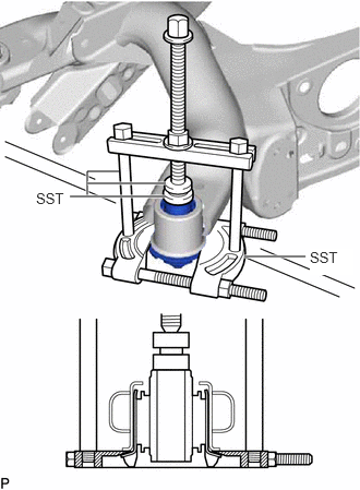
Install SST as shown in the illustration.
- SST
- 09950-00020
09950-00030
09950-60011 (09951-00330)
- NOTICE:
-
Apply molybdenum grease to the threads and tip of the SST center bolt before use.
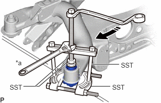
| *a | Hold |
|
|
Turn |
Using SST, remove the rear suspension member rear body mount cushion LH while applying lubricant into the clearance between the rear suspension member rear body mount cushion LH and the rear suspension member sub-assembly.
- SST
- 09950-00020
09950-00030
09950-60011 (09951-00330)
- NOTICE:
- ·
Tighten SST slowly and evenly.
·Be careful as the rear suspension member rear body mount cushion LH may fly out.
·The rear suspension member rear body mount cushion LH cannot be reused.
Remove SST and the rear suspension member rear body mount cushion LH from the rear suspension member sub-assembly.
52275A
34.REMOVE REAR SUSPENSION MEMBER REAR BODY MOUNT CUSHION RH
- HINT:
-
Perform the same procedure as for the LH side.
35.REMOVE HOLE PLUG
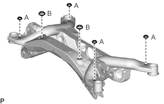
Remove the 6 hole plugs from the rear suspension member sub-assembly.
- HINT:
-
There are 2 different shapes of hole plug.