REAR SUSPENSION REAR LOWER ARM REMOVAL
CAUTION / NOTICE / HINT
The necessary procedures (adjustment, calibration, initialization, or registration) that must be performed after parts are removed and installed, or replaced during rear suspension arm assembly removal/installation are shown below.
| Replaced Part or Performed Procedure | Necessary Procedure | Effect/Inoperative Function when Necessary Procedure not Performed | Link |
|---|---|---|---|
| Rear wheel alignment adjustment | 1.
Perform "Reset Memory" 2.
Perform "Calibration" |
·
DTCs are stored ·
ABS warning light illuminates ·
Brake warning light / yellow (minor malfunction) illuminates ·
Slip indicator light illuminates ·
VSC disabled or malfunctions |
( 202304,999999,_54,_083077,_0401811,RM1000000029TH7,) 202304,999999,_54,_083077,_0401811,RM1000000029TH7,)
|
| Suspension, tires, etc. | Parking assist ECU initialization | Panoramic View Monitor System | (202304,999999,_56,_083082,_0586733,RM1000000029R9F,)
|
| Replaced Part or Performed Procedure | Necessary Procedure | Effect/Inoperative Function when Necessary Procedure not Performed | Link |
|---|---|---|---|
| Rear wheel alignment adjustment | 1.
Perform "Reset Memory" 2.
Perform acceleration sensor zero point calibration and store system information memorization |
·
VSC is disabled or malfunctions ·
DTCs are output ·
Slip indicator light illuminates ·
ABS warning light illuminates |
(202304,999999,_54,_083077,_0402316,RM100000002AG8P,)
|
| Suspension, tires, etc. | Parking assist ECU initialization | Panoramic View Monitor System | (202304,999999,_56,_083082,_0586733,RM1000000029R9F,)
|
- HINT:
- ·
Use the same procedure for the RH side and LH side.
·The following procedure is for the LH side.
PROCEDURE

 1.REMOVE REAR WHEEL
48840A
2.REMOVE REAR STABILIZER LINK ASSEMBLY
48231B
3.REMOVE REAR COIL SPRING
48258C
4.REMOVE REAR LOWER COIL SPRING INSULATOR
48740F
5.REMOVE REAR NO. 2 SUSPENSION ARM ASSEMBLY
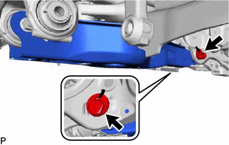
Remove the nut, No. 2 camber adjust cam, rear suspension toe adjust cam sub-assembly and rear No. 2 suspension arm assembly.
- NOTICE:
-
Hold the rear suspension toe adjust cam sub-assembly while rotating the nut.
48720A
6.REMOVE REAR NO. 1 SUSPENSION ARM ASSEMBLY
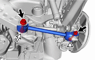
Remove the 2 bolts, 2 nuts and rear No. 1 suspension arm assembly from the rear axle carrier sub-assembly and rear suspension member sub-assembly.
- NOTICE:
-
Because the nut has its own stopper, do not turn the nut. Loosen the bolt with the nut secured.