M20D-FKS ENGINE CONTROL THROTTLE BODY INSTALLATION
CAUTION / NOTICE / HINT
- NOTICE:
-
This procedure includes the installation of small-head bolts. Refer to Small-Head Bolts of Basic Repair Hint to identify the small-head bolts.
- HINT:
-
Perform "Inspection After Repair" after replacing the throttle body with motor assembly.
PROCEDURE

 22030
1.INSTALL THROTTLE BODY WITH MOTOR ASSEMBLY
22030
1.INSTALL THROTTLE BODY WITH MOTOR ASSEMBLY
- HINT:
-
Perform "Inspection After Repair" after replacing the throttle body with motor assembly.
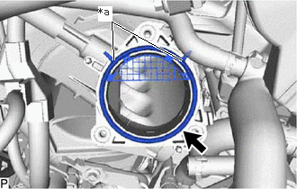
| *a | Protrusion |
Install a new throttle body gasket to the intake manifold with the protrusions of the throttle body gasket oriented as shown in the illustration.
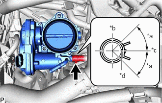
| *a | 45° (Claw of Clip Location) |
| *b | Top |
| *c | Left of Vehicle |
| *d | Paint Mark |
Connect the No. 5 water by-pass hose to the throttle body with motor assembly and slide the clip to secure it.
- NOTICE:
- ·
If the throttle body with motor assembly has been struck or dropped, replace it.
·Make sure to position the clip as shown in the illustration.
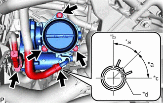
| *a | 45° (Claw of Clip Location) |
| *b | Top |
| *c | Left of Vehicle |
| *d | Paint Mark |
Install the throttle body with motor assembly to the intake manifold with the 3 bolts.
- Torque:
- 10 N*m (102 kgf*cm, 7 ft.*lbf)
Connect the No. 8 water by-pass hose to the throttle body with motor assembly and slide the clip to secure it.
- NOTICE:
-
Make sure to position the clip as shown in the illustration.
Connect the throttle body with motor assembly connector.
2.INSTALL AIR CLEANER ASSEMBLY WITH AIR CLEANER HOSE
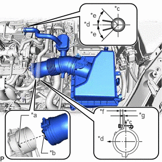
| *a | Protrusion |
| *b | Cutout |
| *c | Top |
| *d | Front of Vehicle |
| *e | 45° (Claw of Clip Location) |
| *f | 6 to 14 mm (0.236 to 0.551 in.) |
| *g | Within 10 mm (0.394 in.) |
Install the air cleaner assembly with air cleaner hose to the throttle body with motor assembly and tighten the hose clamp.
- NOTICE:
-
Align the cutout of the air cleaner hose with the protrusion of the throttle body with motor assembly as shown in the illustration.
Insert the air cleaner assembly with air cleaner hose 3 pins into the air cleaner support.
Connect the No. 2 PCV hose to the cylinder head cover sub-assembly and slide the clip to secure it.
- NOTICE:
-
Make sure to position the clip as shown in the illustration.
Connect the vacuum hose to the air cleaner hose.
Attach the 3 wire harness clamps.
Connect the mass air flow meter sub-assembly connector.
17751
3.INSTALL NO. 1 INLET AIR CLEANER

Install the No. 1 inlet air cleaner with the 2 bolts in the order shown in the illustration.
- Torque:
- 8.0 N*m (82 kgf*cm, 71 in.*lbf)
12601B
4.INSTALL NO. 1 ENGINE COVER SUB-ASSEMBLY
5.ADD ENGINE COOLANT
6.INSPECT FOR COOLANT LEAK