M20D-FKS COOLING RADIATOR INSTALLATION
PROCEDURE

 16897A
1.INSTALL FILLER NECK
16897A
1.INSTALL FILLER NECK

| *a | Retainer |

|
Install in this Direction |

|
Press in this Direction |
Align the filler neck with the radiator assembly and securely insert the filler neck to the radiator assembly.
- NOTICE:
- ·
Confirm that the retainer makes a "click" sound when pushed.
·If the filler neck O-ring is damaged, replace it with a new one.
Push in the retainer.
Check that the radiator assembly and filler neck are securely connected by pulling on them.
16535
2.INSTALL LOWER RADIATOR SUPPORT
Install the 2 lower radiator supports to the radiator assembly.
16523A
3.INSTALL RADIATOR SUPPORT CUSHION
Install the 2 radiator support cushions to the radiator assembly.
16400
4.INSTALL RADIATOR ASSEMBLY
Attach the 2 guides.
Attach the 2 claws to install the fan with motor assembly to the radiator assembly.
- NOTICE:
-
Do not damage the radiator assembly when installing the fan with motor assembly.
Install the radiator assembly with the fan with motor assembly to the vehicle body.
- NOTICE:
-
Do not apply excessive force to the cooler condenser assembly or pipe when installing the radiator assembly with the fan with motor assembly.
Attach the 2 guides.
Attach the 2 claws to install the cooler condenser assembly to the radiator assembly.
- NOTICE:
-
Make sure not to damage the cooler condenser assembly when installing the cooler condenser assembly.
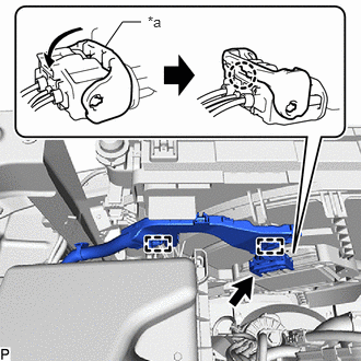
| *a | Lock Lever |
Attach the 2 wire harness clamps.
Connect the cooling fan motor connector and push down the lock lever to attach the claw as shown in the illustration.
- NOTICE:
- ·
When connecting the cooling fan motor connector, make sure that the connecting parts of the cooling fan motor connector are free of dirt, water or other foreign matter.
·Be sure to securely connect the cooling fan motor connector.
16572D
5.CONNECT NO. 2 RADIATOR HOSE
Connect the No. 2 radiator hose to the radiator assembly and slide the clip to secure it.
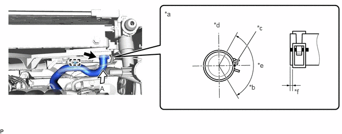
| *a | View A | *b | 120° |
| *c | Paint Mark | *d | Upper Side |
| *e | RH Side | *f | 2 to 5 mm (0.0787 to 0.197 in.) |
- NOTICE:
- ·
Align the direction of the claw on the clip with the paint mark on the hose.
·Make sure the No. 2 radiator hose is securely inserted to the stopper.
Attach the clamp to connect the No. 2 radiator hose to the fan with motor assembly.
16571C
6.CONNECT NO. 1 RADIATOR HOSE
Connect the No. 1 radiator hose to the radiator assembly and slide the clip to secure it.
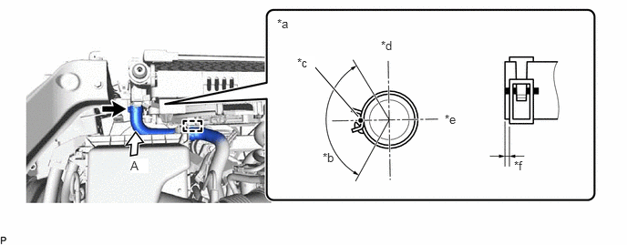
| *a | View A | *b | 120° |
| *c | Paint Mark | *d | Upper Side |
| *e | RH Side | *f | 2 to 5 mm (0.0787 to 0.197 in.) |
- NOTICE:
- ·
Align the direction of the claw on the clip with the paint mark on the hose.
·Make sure the No. 1 radiator hose is securely inserted to the stopper.
Attach the clamp to connect the No. 1 radiator hose to the fan with motor assembly.
16283
7.CONNECT NO. 6 WATER BY-PASS HOSE
Connect the No. 6 water by-pass hose to the radiator assembly.
16282
8.CONNECT NO. 5 WATER BY-PASS HOSE
Connect the No. 5 water by-pass hose to the radiator assembly and slide the clip to secure it.
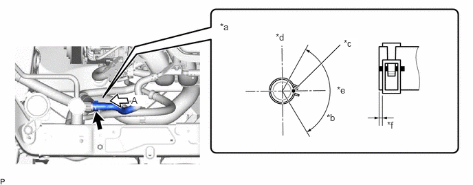
| *a | View A | *b | 120° |
| *c | Paint Mark | *d | Upper Side |
| *e | Rear Side | *f | 2 to 5 mm (0.0787 to 0.197 in.) |
- NOTICE:
- ·
Align the direction of the claw on the clip with the paint mark on the hose.
·Make sure the No. 5 water by-pass hose is securely inserted to the stopper.
53205
9.INSTALL UPPER RADIATOR SUPPORT SUB-ASSEMBLY
Install the upper radiator support sub-assembly with the 4 bolts.
- Torque:
- 12.5 N*m (127 kgf*cm, 9 ft.*lbf)
Attach the 3 clamps to connect the wire harness to the upper radiator support sub-assembly.
Attach the 2 clamps to connect the hood lock control cable assembly to the upper radiator support sub-assembly.
Connect the 2 horn connectors.
53510
10.INSTALL HOOD LOCK ASSEMBLY
16593B
11.INSTALL NO. 1 RADIATOR AIR GUIDE RH
Attach the guide and claw and install the No. 1 radiator air guide RH.
Install the clip.
16595B
12.INSTALL NO. 1 RADIATOR AIR GUIDE LH
Attach the guide and claw and install the No. 1 radiator air guide LH.
Install the clip.
88790B
13.INSTALL THERMISTOR ASSEMBLY
16681A
14.INSTALL UPPER RADIATOR AIR GUIDE PLATE
Install the radiator upper air guide plate with the 5 clips.
17751
15.INSTALL NO. 1 INLET AIR CLEANER
52021
16.INSTALL FRONT BUMPER REINFORCEMENT SUB-ASSEMBLY
52614
17.INSTALL FRONT BUMPER NO. 2 ENERGY ABSORBER
52119A
18.INSTALL FRONT BUMPER COVER
19.ADD ENGINE COOLANT
20.INSPECT FOR COOLANT LEAK
51420
21.INSTALL NO. 2 ENGINE UNDER COVER ASSEMBLY
51441
22.INSTALL NO. 1 ENGINE UNDER COVER
53896B
23.INSTALL FRONT FENDER FRONT SPLASH SHIELD LH
53895B
24.INSTALL FRONT FENDER FRONT SPLASH SHIELD RH