DRIVE SHAFT / PROPELLER SHAFT FRONT DRIVE SHAFT ASSEMBLY(for AWD) REASSEMBLY
CAUTION / NOTICE / HINT
- NOTICE:
- ·
When using a vise, place aluminum plates between the part and vise.
·When using a vise, do not overtighten it.
- HINT:
- ·
Use the same procedure for the RH and LH sides.
·The following procedure is for the LH side.
PROCEDURE

 43410C
1.INSTALL FRONT DRIVE SHAFT BEARING (for RH Side)
43410C
1.INSTALL FRONT DRIVE SHAFT BEARING (for RH Side)
for Gasoline model:
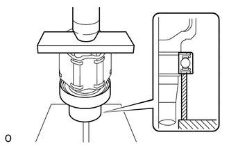
Using SST and a press, press in the front drive inboard joint assembly RH until the new front drive shaft bearing contacts the edge of the front drive inboard joint assembly RH.
- SST
- 09527-10011
09710-30012 (09710-04081)
- NOTICE:
- ·
Make sure the front drive shaft bearing contacts the edge of the front drive inboard joint assembly RH, but do not press it in more than necessary.
·Do not apply weight to the dust cover and outer race of the front drive shaft bearing.
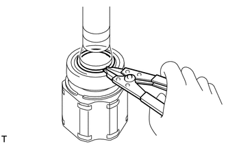
Using a snap ring expander, install a new snap ring.
- NOTICE:
-
The snap ring should be installed completely.
41336D
2.INSTALL FRONT DRIVE SHAFT DUST COVER RH (for Gasoline Model)
Using SST and a press, install a new front drive shaft dust cover RH to the front drive inboard joint assembly RH as shown in the illustration.
- SST
- 09527-10011
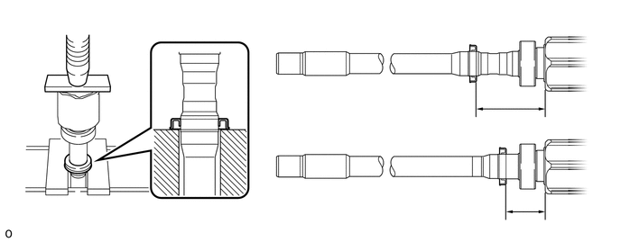
| *A | except Torque Vectoring Differential | *B | for Torque Vectoring Differential |
- Standard distance (A):
for Torque Vectoring Differential 103.5 to 104.5 mm (4.08 to 4.11 in.) except Torque Vectoring Differential 58.5 to 59.5 mm (2.31 to 2.34 in.)
- NOTICE:
- ·
Make sure to install the front drive shaft dust cover RH in the correct direction.
·Do not damage the front drive shaft dust cover RH.
·The front drive shaft dust cover RH should be installed completely.
3.INSTALL FRONT AXLE OUTBOARD JOINT BOOT
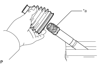
| *a | Protective Tape |
Wrap the splines of the front drive outboard joint shaft assembly with protective tape to prevent the boot from being damaged.
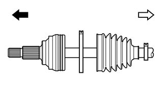
| *1 | Front Drive Outboard Joint Shaft Assembly |
| *2 | Front No. 2 Axle Outboard Joint Boot Clamp |
| *3 | Front Axle Outboard Joint Boot |
| *4 | Front Axle Outboard Joint Boot Clamp |

|
Outboard Joint Side |

|
Inboard Joint Side |
Install new parts to the front drive outboard joint shaft assembly in the following order.
Front No. 2 axle outboard joint boot clamp
Front axle outboard joint boot
Front axle outboard joint boot clamp
Pack the joint portion of the front drive outboard joint shaft assembly and front axle outboard joint boot with grease.
- Dimension (A):
for Gasoline model 105.0 to 115.0 g (3.71 to 4.05 oz) for HV model 205.0 to 215.0 g (7.24 to 7.58 oz)
Install the front axle outboard joint boot to the front drive outboard joint shaft assembly groove.
- NOTICE:
- ·
Do not allow grease to adhere to the boot clamp track of the outboard joint boot.
·Keep the inside of the outboard joint boot free of foreign matter.
43447F
4.INSTALL FRONT NO. 2 AXLE OUTBOARD JOINT BOOT CLAMP
- CAUTION:
- ·
Wear protective gloves when installing the front No. 2 axle outboard joint boot clamp.
·If protective gloves are not worn, injuries may occur.
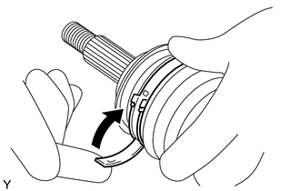
Install the front No. 2 axle outboard joint boot clamp to the front axle outboard joint boot and partially bend down the lever.
- NOTICE:
- ·
Make sure the front No. 2 axle outboard joint boot clamp is positioned correctly within the groove of the front axle outboard joint boot as far toward the inside of the vehicle as possible.
·Before bending the lever, confirm that the front No. 2 axle outboard joint boot clamp and the lever are not deformed or damaged.
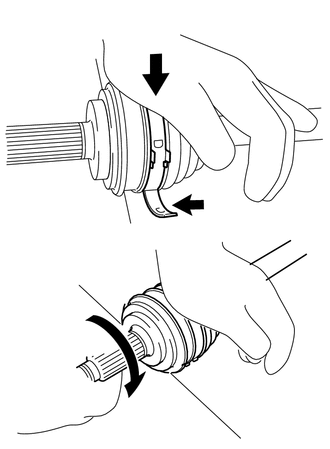
| *a | Weight |
| *b | Contact |
Lean your weight on your hand and roll the outboard joint forward while pressing the outboard joint against the work surface. Roll the outboard joint and fold the lever until a click sound can be heard.
- NOTICE:
- ·
Do not damage the deflector.
·Make sure that the outboard joint is in direct contact with the work surface.
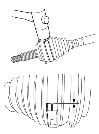
| *a | Buckle |
Using a plastic hammer, bend the buckle to secure the lever and confirm that the tip of the lever is aligned with the buckle as shown in the illustration.
- NOTICE:
- ·
Do not use excessive force when tapping with the plastic hammer.
·Do not damage the front axle outboard joint boot.
43447E
5.INSTALL FRONT AXLE OUTBOARD JOINT BOOT CLAMP
- CAUTION:
- ·
Wear protective gloves when installing the front axle outboard joint boot clamp.
·If protective gloves are not worn, injuries may occur.
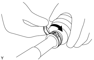
Install the front axle outboard joint boot clamp to the front axle outboard joint boot and partially bend down the lever.
- NOTICE:
- ·
Make sure that the front axle outboard joint boot clamp is correctly positioned within the groove.
·Confirm that the front axle outboard joint boot clamp and lever are not deformed or damaged.
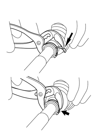
| *a | Place the tip near the center of the lever |
Using water pump pliers, temporarily secure the front axle outboard joint boot clamp by pinching the front axle outboard joint boot clamp until a click sound is heard.
- NOTICE:
-
Do not damage the front axle outboard joint boot.
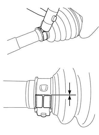
| *a | Buckle |
Using a plastic hammer, bend the buckle to secure the lever and confirm that the tip of the lever is aligned with the buckle as shown in the illustration.
- NOTICE:
- ·
Do not use excessive force when tapping with the plastic hammer.
·Do not damage the front axle outboard joint boot.
43474E
6.INSTALL FRONT DRIVE SHAFT DAMPER (for LH Side)
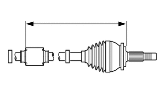
| *1 | Front Drive Shaft Damper Clamp |
| *2 | Front Drive Shaft Damper |
Temporarily install the front drive shaft damper and 2 new front drive shaft damper clamps to the front drive outboard joint shaft assembly as shown in the illustration.
Set the dimension (A) as specified below.
- Dimension (A):
for Gasoline model 256.9 to 260.9 mm (10.12 to 10.27 in.) for HV model 277.9 to 281.9 mm (10.95 to 11.09 in.)
7.INSTALL FRONT DRIVE SHAFT DAMPER CLAMP (for LH Side)
Type A:
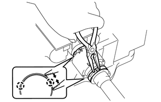
| *a | Claw |
Using needle-nose pliers, engage each claw to install the 2 front drive shaft damper clamps as shown in the illustration.
- NOTICE:
- ·
Be sure to install the clamp in the correct position.
·Do not damage the front drive shaft damper.
·Do not damage the claws.
Type B:
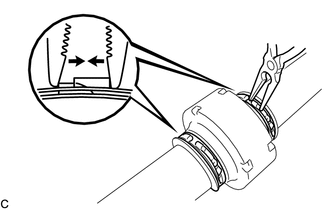
Using needle-nose pliers, install the 2 front drive shaft damper clamps as shown in the illustration.
- NOTICE:
- ·
Be sure to install the clamps in the correct position.
·Do not damage the front drive shaft damper.
43040
8.INSTALL FRONT DRIVE INBOARD JOINT ASSEMBLY
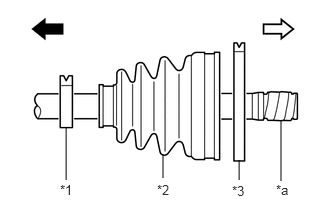
| *1 | Front Axle Inboard Joint Boot Clamp |
| *2 | Front Axle Inboard Joint Boot |
| *3 | Front No. 2 Axle Inboard Joint Boot Clamp |
| *a | Protective Tape |
|
|
Outboard Joint Side |
|
|
Inboard Joint Side |
Install new parts to the front drive outboard joint shaft assembly in the following order:
Front axle inboard joint boot clamp
Front axle inboard joint boot
Front No. 2 axle inboard joint boot clamp
Remove the protective tape.
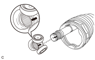
| *a | Matchmark |
Align the matchmarks and install the tripod joint to the front drive outboard joint shaft assembly.
- NOTICE:
-
Face the serrated side of the tripod joint outward and install it to the outboard joint end.
Using a brass bar and a hammer, install the tripod joint to the front drive outboard joint shaft assembly.
- NOTICE:
- ·
Do not tap the rollers.
·Keep the tripod joint free of foreign matter.
·Make sure to install the tripod joint in the correct direction.
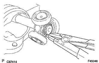
Using a snap ring expander, install a new shaft snap ring to the front drive outboard joint shaft assembly.
Pack the front drive inboard joint assembly and front axle inboard boot with grease.
- Standard Grease Capacity:
205.0 to 215.0 g (7.24 to 7.58 oz)
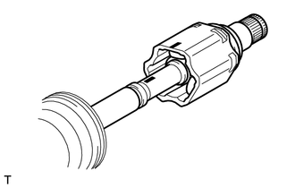
| *a | Matchmark |
Align the matchmarks and install the front drive inboard joint assembly to the front drive outboard joint shaft assembly.
9.INSTALL FRONT AXLE INBOARD JOINT BOOT
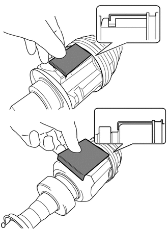
| *A | for LH Side |
| *B | for RH Side |

|
Jig |
Using a jig, install the front axle inboard joint boot to the front drive inboard joint assembly.
- NOTICE:
- ·
Keep the grooves free of grease.
·Keep the inside of the front axle inboard joint boot free of foreign matter.
·If the front axle inboard joint boot is not installed at the position indicated by the jig, damage to the front axle inboard joint boot may result.
·Place the jig at several points around the circumference of the front drive inboard joint assembly to check that the front axle inboard joint boot is installed to the correct position.
Install the front axle inboard joint boot to the front drive inboard joint assembly.
Adjust the position of the front axle inboard joint boot so that the dimension (A) is as specified.
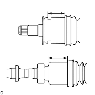
| *A | for LH Side |
| *B | for RH Side |
Adjust the position of the front axle inboard joint boot so that the dimension (A) is as specified.
- Dimension (A):
for LH Side 51.8 to 52.2 mm (2.04 to 2.05 in.) for RH Side 66.8 to 67.2 mm (2.63 to 2.64 in.)
- NOTICE:
- ·
Keep the grooves free of grease.
·Keep the inside of the front axle inboard joint boot free of foreign matter.
·If the front axle inboard joint boot is installed while the dimension (A) is not as specified, damage to the front axle inboard joint boot may result.
43448G
10.INSTALL FRONT NO. 2 AXLE INBOARD JOINT BOOT CLAMP
- CAUTION:
- ·
Wear protective gloves when installing the front No. 2 axle inboard joint boot clamp.
·If protective gloves are not worn, injuries may occur.
- NOTICE:
-
A new front No. 2 axle inboard joint boot clamp is coated with lubricant. Do not remove the lubricant.
Install the front No. 2 axle inboard joint boot clamp to the front axle inboard joint boot.
- HINT:
-
 1.688,0.531 1.958,0.302 false 0.677,0.833 1.083,0.833 false 0.406,2.656 0.938,2.656 false 2,0.188 2.365,0.406 0.365,0.219 10 false *a 0.5,0.729 0.813,0.927 0.313,0.198 10 false *1 0.229,2.552 0.542,2.75 0.313,0.198 10 false *2 1.698,1.094 2.01,1.281 0.313,0.188 10 false A 2.729,3.021 3.042,3.208 0.313,0.188 10 false A 0.635,3.021 0.948,3.208 0.313,0.188 10 false A
*1 Front No. 2 Axle Inboard Joint Boot Clamp *2 Front Axle Inboard Joint Boot *a Bending Point
-
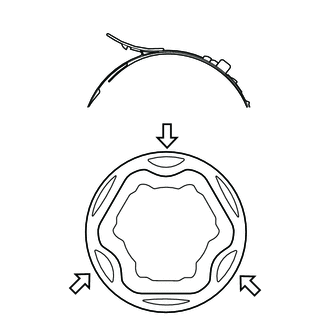
To make installation easier, align the bending point of the lever of the front No. 2 axle inboard joint boot clamp with any of the positions indicated by the arrows (A) shown in the illustration.
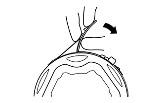
| *a | Welded Area |
Temporarily bend the lever of the front No. 2 axle inboard joint boot clamp.
- NOTICE:
- ·
Make sure the front No. 2 axle inboard joint boot clamp is positioned correctly within the groove of the front axle inboard joint boot as far toward the inside of the vehicle as possible.
·Before bending the lever, confirm that the front No. 2 axle inboard joint boot clamp and the lever are not deformed or damaged.
- HINT:
-
When temporarily bending the lever, push the lever at the welded area.
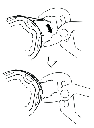
Using water pump pliers, temporarily secure the front No. 2 axle inboard joint boot clamp by pinching the front No. 2 axle inboard joint boot clamp until a click sound is heard.
- NOTICE:
- ·
Do not damage the front axle inboard joint boot.
·To avoid deformation of the front No. 2 axle inboard joint boot clamp, set one tip of the water pump pliers on the welded area of the lever.
- HINT:
- ·
As the front No. 2 axle inboard joint boot clamp is tightened, the tip of the water pump pliers will slide along the front No. 2 axle inboard joint boot clamp until it contacts the protrusion.
·Set the water pump pliers to an appropriate size before tightening the front No. 2 axle inboard joint boot clamp.
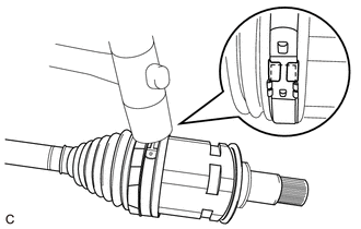
| *a | Buckle |
Using a plastic hammer, bend the buckle to secure the lever.
- NOTICE:
- ·
Do not use excessive force when tapping with the plastic hammer.
·Do not damage the front axle inboard joint boot.
·Check the front axle inboard joint boot is installed to the correct position.
43448F
11.INSTALL FRONT AXLE INBOARD JOINT BOOT CLAMP
- NOTICE:
-
A new front axle inboard joint boot clamp is coated with lubricant. Do not remove the lubricant.
Check whether the drive shaft dimension (A) are within specification.
- NOTICE:
-
Keep the drive shaft assembly level during inspection.
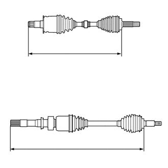
| *A | for LH Side |
| *B | for RH Side |
for Gasoline model:
- Dimension (A):
for LH Side 603.2 mm (1.98 ft.) for RH Side 905.0 mm (2.97 ft.)
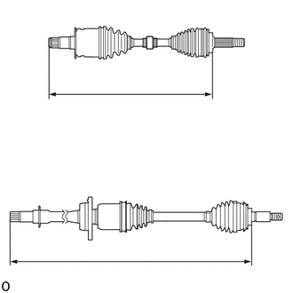
| *A | for LH Side |
| *B | for RH Side |
for HV model:
- Dimension (A):
for LH Side 607.6 mm (1.99 ft.) for RH Side 906.4 mm (2.97 ft.)
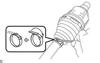
Using a screwdriver, install the front axle inboard joint boot clamp.
- NOTICE:
-
Do not damage the front axle inboard joint boot.
12.INSPECT FRONT DRIVE SHAFT ASSEMBLY