M20D-FKS ENGINE MECHANICAL ENGINE UNIT DISASSEMBLY
CAUTION / NOTICE / HINT
- NOTICE:
-
This procedure includes the installation of small-head bolts. Refer to Small-Head Bolts of Basic Repair Hint to identify the small-head bolts.
PROCEDURE

 19100P
1.REMOVE SPARK PLUG
19100P
1.REMOVE SPARK PLUG
89615
2.REMOVE KNOCK CONTROL SENSOR
89448D
3.REMOVE OIL PRESSURE AND TEMPERATURE SENSOR
15250
4.REMOVE OIL PRESSURE CONTROL VALVE ASSEMBLY
11102A
5.REMOVE CAMSHAFT POSITION SENSOR (for Intake Side)
11102A
6.REMOVE CAMSHAFT POSITION SENSOR (for Exhaust Side)
15370
7.REMOVE CAM TIMING OIL CONTROL SOLENOID ASSEMBLY
13090D
8.REMOVE CAM TIMING CONTROL MOTOR WITH EDU ASSEMBLY
15710
9.REMOVE OIL COOLER ASSEMBLY
16261G
10.REMOVE NO. 1 WATER BY-PASS HOSE
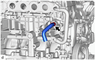
Slide the clip and remove the No. 1 water by-pass hose from the cylinder block sub-assembly.
16264
11.REMOVE NO. 2 WATER BY-PASS HOSE
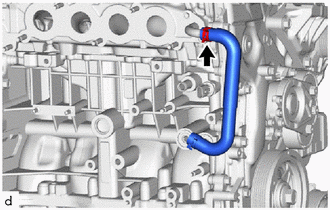
Slide the clip and remove the No. 2 water by-pass hose from the water by-pass pipe sub-assembly.
12180E
12.REMOVE OIL FILLER CAP ASSEMBLY
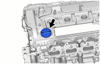
Remove the oil filler cap sub-assembly from the cylinder head cover sub-assembly.
12108A
13.REMOVE OIL FILLER CAP GASKET
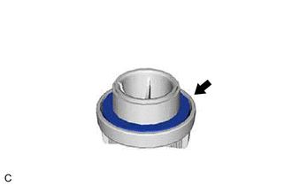
Remove the oil filler cap gasket from the oil filler cap sub-assembly.
11401G
14.REMOVE CRANKSHAFT POSITION SENSOR
12204C
15.REMOVE PCV VALVE (VENTILATION VALVE SUB-ASSEMBLY)
29300
16.REMOVE VACUUM PUMP ASSEMBLY
13470
17.REMOVE CRANKSHAFT PULLEY ASSEMBLY
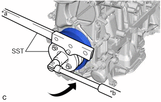
| *a | Hold |
| *b | Turn |
Using SST, hold the crankshaft pulley assembly and loosen the crankshaft pulley bolt. Further loosen the crankshaft pulley bolt until 2 or 3 threads remain screwed into the crankshaft.
- SST
- 09213-54015
09330-00021
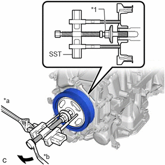
| *1 | Crankshaft Pulley Bolt |
| *a | Hold |
| *b | Turn |
Using SST and the crankshaft pulley bolt, remove the crankshaft pulley assembly and crankshaft pulley bolt.
- SST
- 09950-50013 (09951-05010, 09952-05010, 09953-05020, 09954-05070, 09957-04010)
- HINT:
-
Apply lubricant to the threads and end of SST.
16331
18.REMOVE WATER OUTLET
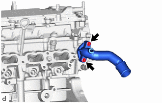
Remove the 2 bolts, water outlet and water outlet gasket from the cylinder head sub-assembly.
16305E
19.REMOVE OUTLET WATER BY-PASS SUB-ASSEMBLY
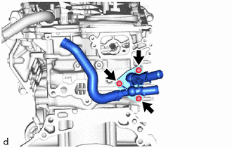
Remove the 3 bolts, outlet water by-pass sub-assembly and outlet water pipe gasket from the cylinder head sub-assembly.
11201
20.REMOVE CYLINDER HEAD COVER SUB-ASSEMBLY
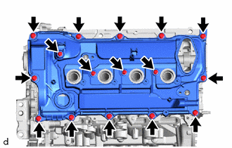
Remove the 16 bolts and cylinder head cover sub-assembly from the camshaft housing sub-assembly.
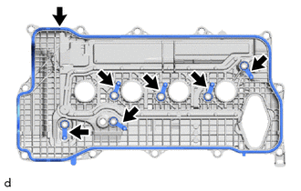
Remove the 7 cylinder head cover gaskets from the cylinder head cover sub-assembly.
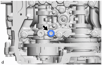
Remove the camshaft bearing cap oil hole gasket from the No. 1 camshaft bearing cap.
11193
21.REMOVE SPARK PLUG TUBE GASKET
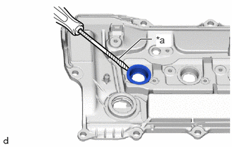
| *a | Protective Tape |
Using a screwdriver, pry out the 4 spark plug tube gaskets from the cylinder head cover sub-assembly.
- NOTICE:
-
Be careful not to damage the cylinder head cover sub-assembly.
- HINT:
-
Tape the screwdriver tip before use.
12315A
22.REMOVE ENGINE MOUNTING BRACKET RH
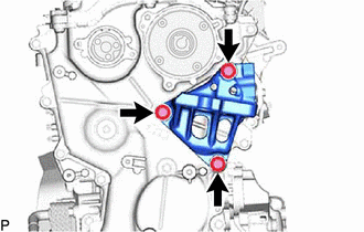
Remove the 3 bolts and engine mounting bracket RH from the No. 2 timing chain cover assembly.
23.REMOVE STRAIGHT SCREW PLUG
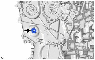
Using a 10 mm hexagon wrench, remove the straight screw plug from the No. 2 timing chain cover assembly.
11320B
24.REMOVE NO. 2 TIMING CHAIN COVER ASSEMBLY

Remove the 20 bolts.
Remove the No. 2 timing chain cover assembly from the timing chain cover assembly by prying the No. 2 timing chain cover assembly with a screwdriver with its tip wrapped with protective tape.
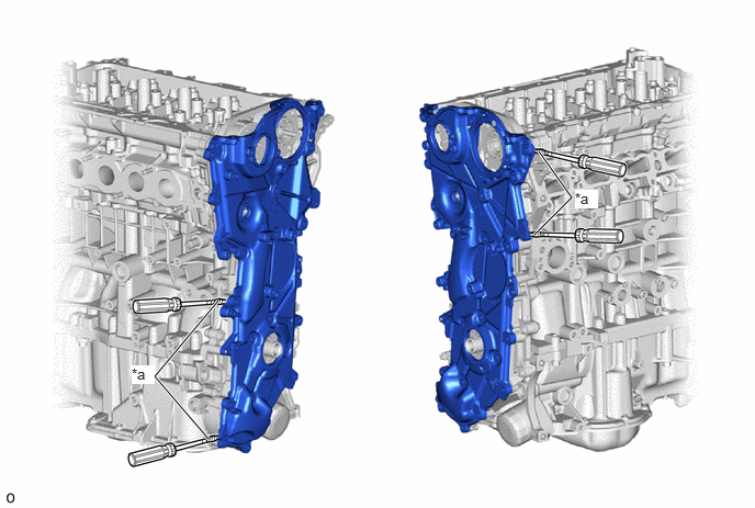
| *a | Protective Tape | - | - |
- NOTICE:
-
Be careful not to damage the contact surfaces of the No. 2 timing chain cover assembly and timing chain cover assembly.
11301C
25.REMOVE TIMING CHAIN COVER OIL SEAL
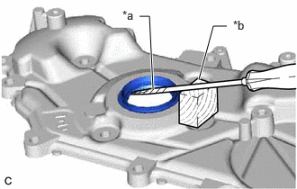
| *a | Protective Tape |
| *b | Wooden Block |
Using a screwdriver and wooden block, pry out the timing chain cover oil seal.
- NOTICE:
-
Do not damage the surface of the timing chain cover oil seal press fit hole.
- HINT:
-
Tape the screwdriver tip before use.
26.SET NO. 1 CYLINDER TO TDC (COMPRESSION)
Temporarily install the crankshaft pulley bolt.
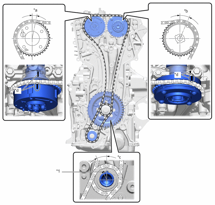
| *1 | Crankshaft Timing Gear Key | - | - |
| *a | Approximately 4.63° | *b | Approximately 33.07° |
| *c | Approximately 2.73° | *d | Timing Mark |
Rotate the crankshaft clockwise and align the crankshaft timing gear key as shown in the illustration.
Check that the timing marks on the camshaft timing exhaust gear assembly and camshaft timing gear assembly are as shown in the illustration.
Remove the crankshaft pulley bolt.
- HINT:
-
As the exhaust camshaft sub-assembly may rotate counterclockwise strongly when the crankshaft pulley bolt is removed, use a wrench to hold the hexagonal portion of the exhaust camshaft sub-assembly.
13507A
27.REMOVE OIL PUMP DRIVE CHAIN SUB-ASSEMBLY
Temporarily install the crankshaft pulley assembly with the crankshaft pulley bolt.
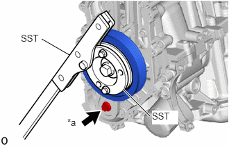
| *a | Bolt |
While holding the crankshaft pulley assembly with SST, remove the bolt.
- SST
- 09213-54015
09330-00021
Remove SST, the crankshaft pulley bolt and crankshaft pulley assembly.
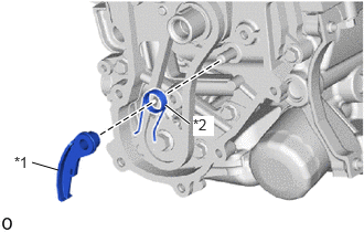
| *1 | Chain Tensioner Plate |
| *2 | Chain Damper Spring |
Remove the chain tensioner plate and chain damper spring.
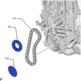
| *1 | Oil Pump Drive Chain Sub-assembly |
| *2 | Oil Pump Drive Sprocket |
| *3 | Oil Pump Drive Shaft Sprocket |
Remove the oil pump drive sprocket, oil pump drive shaft sprocket and oil pump drive chain sub-assembly.
13050
28.REMOVE CAMSHAFT TIMING GEAR ASSEMBLY
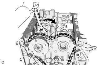
| *a | Loosen |

|
Turn |
Hold the hexagonal portion of the exhaust camshaft sub-assembly with a wrench and turn the camshaft timing gear assembly clockwise to loosen the chain sub-assembly between the camshaft timing exhaust gear assembly and camshaft timing gear assembly.
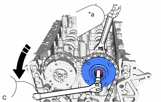
| *a | Hold |
|
|
Turn |
Using a wrench, hold the hexagonal portion of the intake camshaft sub-assembly.
- NOTICE:
- ·
Be careful not to damage the camshaft housing sub-assembly, cylinder head sub-assembly and spark plug tube with the wrench.
·Do not disassemble the camshaft timing gear assembly.
Using a 10 mm bi-hexagonal wrench, remove the bolt and camshaft timing gear assembly from the intake camshaft sub-assembly.
13506
29.REMOVE CHAIN SUB-ASSEMBLY
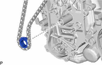
Remove the crankshaft timing sprocket and chain sub-assembly.
13540
30.REMOVE NO. 1 CHAIN TENSIONER ASSEMBLY
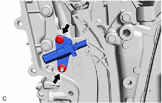
Remove the bolt.
Remove the nut and No. 1 chain tensioner assembly from the timing chain cover assembly.
- NOTICE:
-
Make sure that the plunger, check ball assembly and spring do not come out.
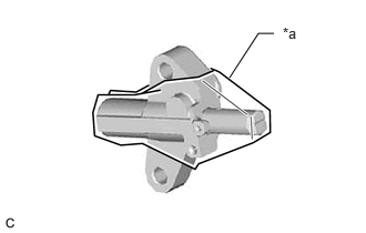
| *a | Tape |
Use tape to hold the plunger inside the No. 1 chain tensioner assembly.
- NOTICE:
- ·
Make sure that the plunger, check ball assembly and spring do not come out.
·If the No. 1 chain tensioner assembly comes apart, reinstall the parts as shown in the illustration.
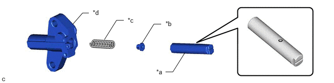 3.552,1.552 3.708,1.552 3.708,1.552 3.969,1.135 false 3.042,0.938 3.302,0.521 3.302,0.521 3.458,0.521 false 2.24,0.854 2.5,0.438 2.5,0.438 2.656,0.438 false 1.563,0.521 1.771,0.281 1.771,0.281 1.906,0.281 false 3.354,1.469 3.667,1.667 0.313,0.198 10 false *a 3.552,0.427 3.865,0.625 0.313,0.198 10 false *b 2.74,0.354 3.052,0.552 0.313,0.198 10 false *c 1.99,0.188 2.302,0.385 0.313,0.198 10 false *d
*a Plunger *b Check Ball Assembly *c Spring *d No. 1 Chain Tensioner Assembly Body
13559
31.REMOVE CHAIN TENSIONER SLIPPER
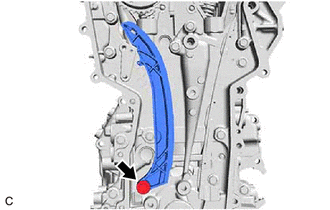
Remove the bolt and chain tensioner slipper from the timing chain cover assembly.
13561
32.REMOVE NO. 1 CHAIN VIBRATION DAMPER
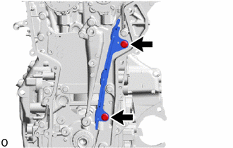
Remove the 2 bolts and No. 1 chain vibration damper from the timing chain cover assembly.
13070A
33.REMOVE CAMSHAFT TIMING EXHAUST GEAR ASSEMBLY
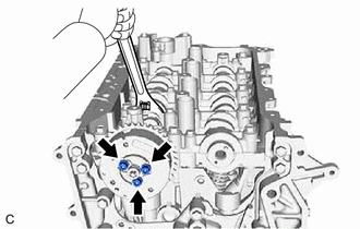
Using a wrench, hold the hexagonal portion of the exhaust camshaft sub-assembly.
- NOTICE:
-
Be careful not to damage the camshaft housing sub-assembly, cylinder head sub-assembly or spark plug tube with the wrench.
Using a 5 mm hexagon socket wrench, remove the 3 bolts.
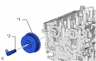
| *1 | Camshaft Timing Exhaust Gear Assembly |
| *2 | Camshaft Timing Oil Control Valve Assembly (Exhaust Camshaft Timing Gear Bolt Assembly) |
Remove the camshaft timing exhaust gear assembly and camshaft timing oil control valve assembly (exhaust camshaft timing gear bolt assembly) from the exhaust camshaft sub-assembly.
11310
34.REMOVE TIMING CHAIN COVER ASSEMBLY
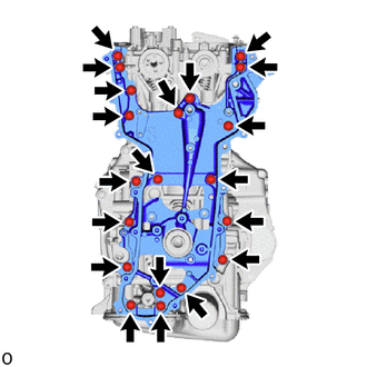
Remove the 20 bolts and timing chain cover assembly from the camshaft housing sub-assembly, cylinder head sub-assembly, cylinder block sub-assembly, stiffening crankcase assembly and oil pump assembly.
Remove the timing chain cover assembly by prying between the cylinder head sub-assembly, camshaft housing sub-assembly, cylinder block sub-assembly and stiffening crankcase assembly with a screwdriver with its tip wrapped with protective tape.
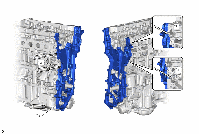
| *a | Protective Tape | - | - |
- NOTICE:
-
Be careful not to damage the contact surfaces of the cylinder head sub-assembly, camshaft housing sub-assembly, cylinder block sub-assembly, stiffening crankcase assembly and timing chain cover assembly.
15703A
35.REMOVE OIL NOZZLE VALVE SUB-ASSEMBLY
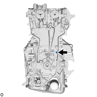
Remove the oil nozzle valve sub-assembly from the cylinder block sub-assembly.
13471A
36.REMOVE CRANKSHAFT TIMING GEAR KEY
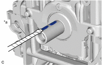
| *a | Protective Tape |
Using a screwdriver, remove the 2 crankshaft timing gear keys from the crankshaft.
- HINT:
-
Tape the screwdriver tip before use.
23477
37.REMOVE FUEL PUMP LIFTER GUIDE
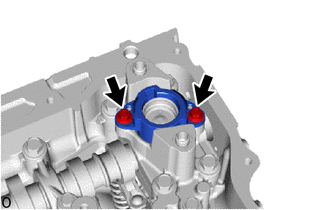
Remove the 2 bolts and fuel pump lifter guide from the No. 4 camshaft bearing cap.
11103
38.REMOVE CAMSHAFT HOUSING SUB-ASSEMBLY
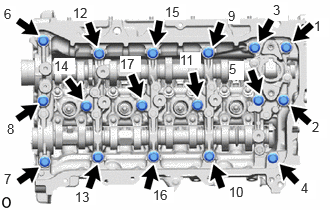
Uniformly loosen and remove the 17 bolts in the order shown in the illustration.

Remove the camshaft housing sub-assembly by prying between the cylinder head sub-assembly and camshaft housing sub-assembly with a screwdriver.
- NOTICE:
-
Be careful not to damage the contact surfaces of the cylinder head sub-assembly and camshaft housing sub-assembly.
- HINT:
-
Tape the screwdriver tip before use.
39.REMOVE CAMSHAFT BEARING CAP
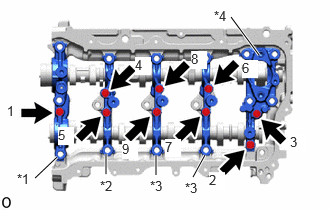
| *1 | No. 1 Camshaft Bearing Cap |
| *2 | No. 2 Camshaft Bearing Cap |
| *3 | No. 3 Camshaft Bearing Cap |
| *4 | No. 4 Camshaft Bearing Cap |
Remove the 9 bolts in the order shown in the illustration.
Remove the No. 1 camshaft bearing cap, No. 2 camshaft bearing cap, 2 No. 3 camshaft bearing caps and No. 4 camshaft bearing cap from the camshaft housing sub-assembly.
- HINT:
-
Arrange the removed parts in such a way that they can be reinstalled to their original locations.
13501A
40.REMOVE INTAKE CAMSHAFT SUB-ASSEMBLY
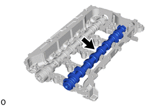
Remove the intake camshaft sub-assembly from the camshaft housing sub-assembly.
13502B
41.REMOVE EXHAUST CAMSHAFT SUB-ASSEMBLY
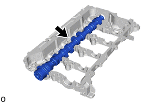
Remove the exhaust camshaft sub-assembly from the camshaft housing sub-assembly.
11155B
42.REMOVE CAMSHAFT BEARING CAP SETTING RING PIN
- NOTICE:
-
It is not necessary to remove the camshaft bearing cap setting ring pins unless they are being replaced.
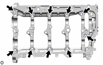
Remove the 10 camshaft bearing cap setting ring pins from the camshaft housing sub-assembly.
13801
43.REMOVE NO. 1 VALVE ROCKER ARM SUB-ASSEMBLY
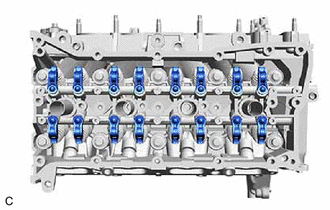
Remove the 16 No. 1 valve rocker arm sub-assemblies from the cylinder head sub-assembly.
- HINT:
-
Arrange the removed parts in such a way that they can be reinstalled to their original locations.
13750
44.REMOVE VALVE LASH ADJUSTER ASSEMBLY
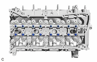
Remove the 16 valve lash adjuster assemblies from the cylinder head sub-assembly.
- HINT:
-
Arrange the removed parts in such a way that they can be reinstalled to their original locations.
13716
45.REMOVE VALVE STEM CAP
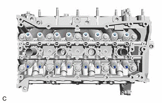
Remove the 16 valve stem caps from the cylinder head sub-assembly.
- HINT:
-
Arrange the removed parts in such a way that they can be reinstalled to their original locations.
16268
46.REMOVE NO. 1 WATER BY-PASS PIPE
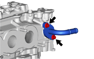
Remove the 2 bolts, No. 1 water by-pass pipe and gasket from the cylinder head sub-assembly.
11101
47.REMOVE CYLINDER HEAD SUB-ASSEMBLY
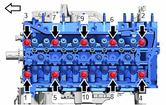

|
Front of Engine |
Uniformly loosen the 10 cylinder head set bolts in the order shown in the illustration. Remove the 10 cylinder head set bolts and 10 plate washers.
- NOTICE:
- ·
Be careful not to drop the plate washers into the cylinder head sub-assembly.
·Warpage or cracking of the cylinder head sub-assembly may result from removing the cylinder head set bolts in the incorrect order.
- HINT:
-
Arrange the removed parts in such a way that they can be reinstalled to their original locations.
Remove the cylinder head sub-assembly from the cylinder block sub-assembly.
11115
48.REMOVE CYLINDER HEAD GASKET
11445
49.REMOVE CYLINDER BLOCK WATER JACKET SPACER
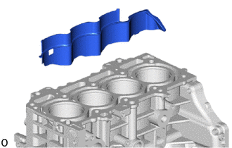
Remove the cylinder block water jacket spacer from the cylinder block sub-assembly.
- NOTICE:
-
Be sure to remove the cylinder block water jacket spacer. If it is not removed, it may fall and become damaged when the cylinder block sub-assembly is inverted.
15601
50.REMOVE OIL FILTER SUB-ASSEMBLY
15600A
51.REMOVE OIL FILTER UNION
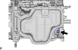
Using a 12 mm hexagon socket wrench, remove the oil filter union from the stiffening crankcase assembly.
12101A
52.REMOVE OIL PAN DRAIN PLUG
Remove the oil pan drain plug and gasket from the No. 2 oil pan sub-assembly.
12101
53.REMOVE OIL PAN SUB-ASSEMBLY
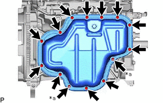
| *a | Nut |
Remove the 12 bolts and 2 nuts.
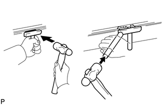
Insert the blade of an oil pan seal cutter between the No. 2 oil pan sub-assembly and stiffening crankcase assembly, cut through the applied sealer and remove the No. 2 oil pan sub-assembly.
- NOTICE:
- ·
Be careful not to damage the contact surfaces of the stiffening crankcase assembly and No. 2 oil pan sub-assembly.
·Be careful not to damage the No. 2 oil pan sub-assembly flange.
15104
54.REMOVE OIL STRAINER SUB-ASSEMBLY
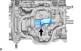
Remove the bolt, oil strainer sub-assembly and oil strainer gasket from the stiffening crankcase assembly.
15520B
55.REMOVE CRANKCASE CAP ASSEMBLY
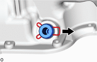
Remove the clip from the crankcase cap assembly.
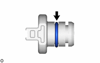
Remove the O-ring from the crankcase cap assembly.
13620B
56.REMOVE ENGINE BALANCER ASSEMBLY
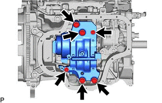
Remove the 6 bolts and engine balancer assembly from the stiffening crankcase assembly.
- NOTICE:
-
Do not disassemble the engine balancer assembly.
15100
57.REMOVE OIL PUMP ASSEMBLY
11420
58.REMOVE STIFFENING CRANKCASE ASSEMBLY
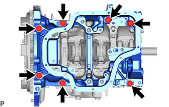
Remove the 7 bolts.
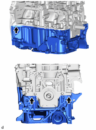
Using a screwdriver, remove the stiffening crankcase assembly by prying between the stiffening crankcase assembly and cylinder block sub-assembly at the places shown in the illustration.
- NOTICE:
-
Be careful not to damage the contact surfaces of the cylinder block sub-assembly and stiffening crankcase assembly.
- HINT:
-
Tape the screwdriver tip before use.
59.REMOVE STRAIGHT SCREW PLUG
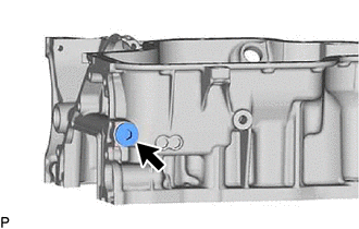
Using a 10 mm hexagon socket wrench, remove the straight screw plug and gasket from the stiffening crankcase assembly.
60.REMOVE STUD BOLT
- NOTICE:
-
If a stud bolt is deformed or its threads are damaged, replace it.
61.REMOVE RING PIN
- NOTICE:
-
It is not necessary to remove the ring pins unless they are being replaced.
62.REMOVE STRAIGHT PIN
- NOTICE:
-
It is not necessary to remove the straight pins unless they are being replaced.
11401L
63.REMOVE REAR ENGINE OIL SEAL
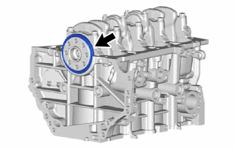
Remove the rear engine oil seal from the cylinder block sub-assembly.