INTERIOR PANELS / TRIM INSTRUMENT PANEL SAFETY PAD DISASSEMBLY
PROCEDURE

 55950G
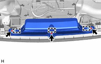
1.REMOVE DEFROSTER NOZZLE ASSEMBLY
55950G
1.REMOVE DEFROSTER NOZZLE ASSEMBLY

|
Screw <A> |
Remove the 3 screws <A>.
Detach the guide and remove the defroster nozzle assembly.
55084E
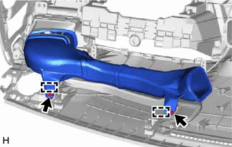
2.REMOVE NO. 1 HEATER TO REGISTER DUCT SUB-ASSEMBLY
|
|
Screw <A> |
Remove the 2 screws <A>.
Detach the guide and remove the No. 1 heater to register duct sub-assembly.
55971C
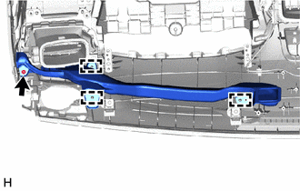
3.REMOVE NO. 1 SIDE DEFROSTER NOZZLE DUCT
|
|
Screw <A> |
Remove the screw <A>.
Detach the guide and remove the No. 1 side defroster nozzle duct.
55650
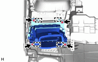
4.REMOVE NO. 1 INSTRUMENT PANEL REGISTER ASSEMBLY
|
|
Screw <A> |
Remove the 4 screws <A>.
Detach the guide and remove the No. 1 instrument panel register assembly.
55961B
5.REMOVE NO. 1 SIDE DEFROSTER NOZZLE
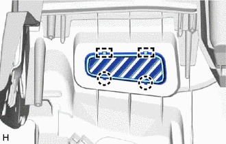
Detach the claw and guide and remove the No. 1 side defroster nozzle.
55086
6.REMOVE NO. 3 HEATER TO REGISTER DUCT SUB-ASSEMBLY
w/o Ion Generator:
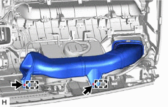
|
|
Screw <A> |
Remove the 2 screws <A>.
Detach the guide and remove the No. 3 heater to register duct sub-assembly.
w/ Ion Generator:
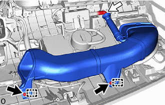
|
|
Screw <A> |

|
Hose |
Remove the 2 screws <A>.
Detach the hose and guide and remove the No. 3 heater to register duct sub-assembly.
87201N
7.REMOVE AIR DUCT SUB-ASSEMBLY (w/ Ion Generator)
88905
8.REMOVE NO. 1 AIR PURIFIER WIRE SUB-ASSEMBLY (w/ Ion Generator, for SFTM Made)
82144
9.REMOVE NO. 4 INSTRUMENT PANEL WIRE (w/ Ion Generator, for GTMC Made)
- HINT:
-
Use the same procedure described as for the No. 1 air purifier wire sub-assembly.
88051A
10.REMOVE ION GENERATOR SUB-ASSEMBLY (w/ Ion Generator)
88995
11.REMOVE NO. 1 ION GENERATOR BRACKET (w/ Ion Generator)
55972C
12.REMOVE NO. 2 SIDE DEFROSTER NOZZLE DUCT
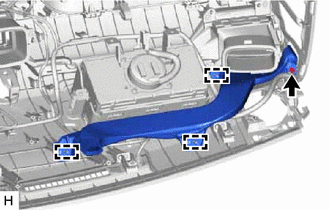
|
|
Screw <A> |
Remove the screw <A>.
Detach the guide and remove the No. 2 side defroster nozzle duct.
55660
13.REMOVE NO. 2 INSTRUMENT PANEL REGISTER ASSEMBLY
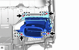
|
|
Screw <A> |
Remove the 4 screws <A>.
Detach the guide and remove the No. 2 instrument panel register assembly.
55962D
14.REMOVE NO. 2 SIDE DEFROSTER NOZZLE
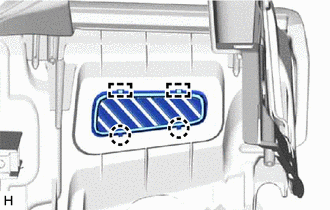
Detach the claw and guide and remove the No. 2 side defroster nozzle.
73960A
15.REMOVE INSTRUMENT PANEL PASSENGER AIRBAG ASSEMBLY
16.REMOVE NAVIGATION ANTENNA ASSEMBLY WITH BRACKET
86101
17.REMOVE ANTENNA CORD SUB-ASSEMBLY
86713
18.REMOVE TELEPHONE ECU WIRE (for Type A)
86203W
19.REMOVE RADIO WIRING SUB-ASSEMBLY (for Type B)
55670A
20.REMOVE CENTER INSTRUMENT PANEL REGISTER ASSEMBLY
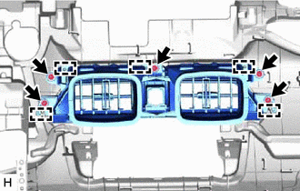
|
|
Screw <A> |
Remove the 5 screws <A>.
Detach the guide and remove the center instrument panel register assembly.
55042B
21.REMOVE NO. 2 INSTRUMENT PANEL BOX DOOR SUB-ASSEMBLY
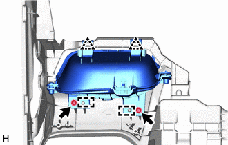
|
|
Screw <A> |
Remove the 2 screws <A>.
Detach the clip and guide and remove the No. 2 instrument panel box door sub-assembly.
55041B
22.REMOVE NO. 1 INSTRUMENT PANEL BOX DOOR SUB-ASSEMBLY
w/ Interior Illumination:
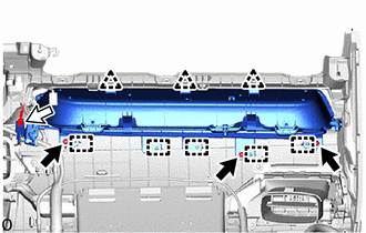
|
|
Screw <A> |
|
|
Connector |
Disconnect the connector.
Remove the 3 screws <A>.
Detach the clip and guide and remove the No. 1 instrument panel box door sub-assembly.
w/o Interior Illumination:
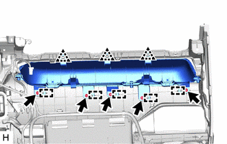
|
|
Screw <A> |
Remove the 5 screws <A>.
Detach the clip and guide and remove the No. 1 instrument panel box door sub-assembly.
89120A
23.REMOVE AUTOMATIC LIGHT CONTROL SENSOR
82143
24.REMOVE NO. 3 INSTRUMENT PANEL WIRE
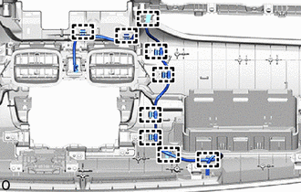
Detach the clamp and remove the No. 3 instrument panel wire.
55981
25.REMOVE NO. 1 DEFROSTER NOZZLE GARNISH
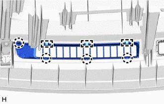
Detach the claw and guide and remove the No. 1 defroster nozzle garnish.
55982
26.REMOVE NO. 2 DEFROSTER NOZZLE GARNISH
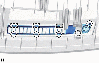
Detach the claw and guide and remove the No. 2 defroster nozzle garnish.
55328
27.REMOVE NO. 1 INSTRUMENT PANEL PIN
Remove the 4 screws <A>.
Detach the guide and remove the 4 No. 1 instrument panel pins.
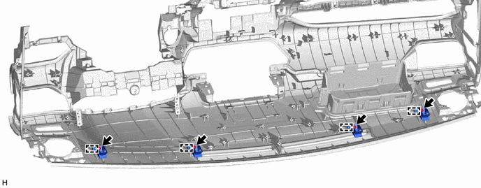
|
|
Screw <A> | - | - |
83107A
28.REMOVE NO. 1 METER BRACKET SUB-ASSEMBLY
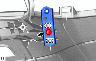
|
|
Screw <A> |
for LH Side:
Remove the screw <A>.
Detach the guide and remove the No. 1 meter bracket sub-assembly.
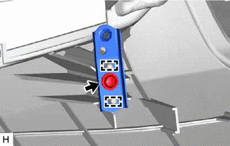
|
|
Screw <A> |
for RH Side:
Remove the screw <A>.
Detach the guide and remove the No. 1 meter bracket sub-assembly.
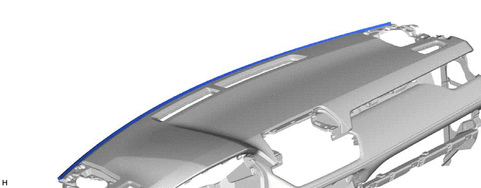
55349C
29.REMOVE INSTRUMENT PANEL CUSHION
Remove the instrument panel cushion.
55557A
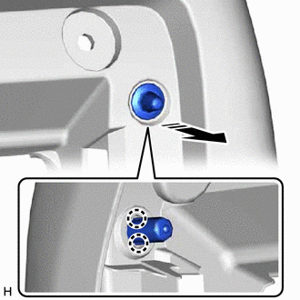
30.REMOVE GLOVE COMPARTMENT DOOR CHECK CUSHION

|
Remove in this Direction |
Detach the claw and remove the glove compartment door check cushion.
- HINT:
-
Use the same procedure to remove the glove compartment door check cushion on the other side.