M20D-FKS BATTERY / CHARGING GENERATOR REASSEMBLY
PROCEDURE

 27310B
1.INSTALL GENERATOR DRIVE END FRAME BEARING
27310B
1.INSTALL GENERATOR DRIVE END FRAME BEARING
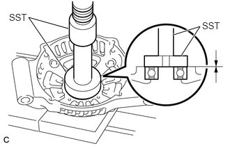
Using SST and a press, install a new generator drive end frame bearing.
- SST
- 09950-60011 (09951-00470)
09950-70010 (09951-07100)
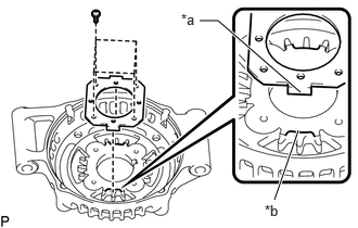
| *a | Tab |
| *b | Cutout |
Fit the tabs of the retainer plate into the cutouts of the generator drive end frame to install the retainer plate.
Install the 4 screws.
- Torque:
- 2.3 N*m (23 kgf*cm, 20 in.*lbf)
27330
2.INSTALL GENERATOR ROTOR ASSEMBLY
Place the generator drive end frame on the generator pulley with clutch.

| *1 | Generator Rotor Assembly |
| *2 | Generator Drive End Frame |
Install the generator rotor assembly to the generator drive end frame.
27360
3.INSTALL GENERATOR COIL ASSEMBLY
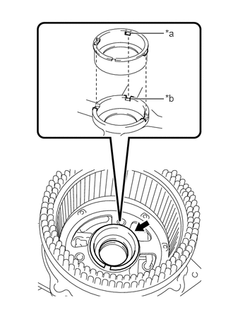
| *a | Protrusion |
| *b | Groove |
Install a new bearing cover packing.
- NOTICE:
-
Align the protrusions of the bearing cover packing with the grooves of the generator coil assembly when installing.
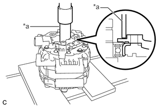
| *a | 21 mm Deep Socket Wrench |
Using a 21 mm deep socket wrench and press, slowly press in the generator coil assembly.
Install the 4 bolts.
- Torque:
- 5.6 N*m (57 kgf*cm, 50 in.*lbf)
27370A
4.INSTALL GENERATOR BRUSH HOLDER ASSEMBLY
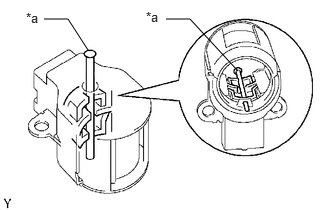
| *a | Pin (1.0 mm) |
While pushing the 2 brushes into the generator brush holder assembly, insert a 1.0 mm (0.0394 in.) pin into the generator brush holder assembly hole.
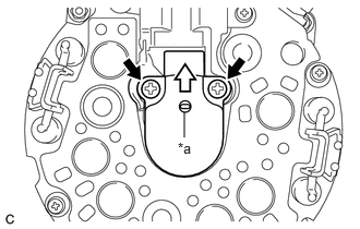
| *a | Pin (1.0 mm) |

|
Pull out |
Install the generator brush holder assembly to the generator coil assembly with the 2 screws.
- Torque:
- 1.8 N*m (18 kgf*cm, 16 in.*lbf)
Pull out the pin from the generator brush holder assembly hole.
27387B
5.INSTALL GENERATOR TERMINAL INSULATOR
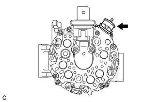
Install the generator terminal insulator to the generator coil assembly.
- NOTICE:
-
Be sure to install the generator terminal insulator in the correct orientation.
27039
6.INSTALL GENERATOR REAR END COVER
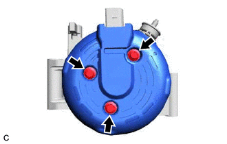
Install the generator rear end cover to the generator coil assembly with the 3 bolts.
- Torque:
- 4.6 N*m (47 kgf*cm, 41 in.*lbf)
27411
7.INSTALL GENERATOR PULLEY
Secure the generator drive end frame in a vise between aluminum plates.
- NOTICE:
-
Do not overtighten the vise.
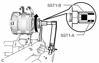
| *a | Hold |
| *b | Turn |
Temporarily install the generator pulley to the rotor shaft with the generator pulley nut.
Fit the rotor shaft end into SST1-A and SST1-B.
- SST
- 09820-63011 (09820-06010, 09820-06021)
- HINT:
SST1-A, SST1-B 09820-06010 SST2 09820-06021
Hold SST1-A with a torque wrench and turn SST1-B clockwise with the specified torque.
- Torque:
- 39 N*m (398 kgf*cm, 29 ft.*lbf)
- NOTICE:
-
Make sure that SST is secured to the rotor shaft end.
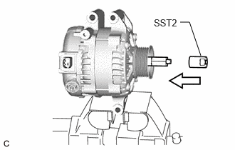
Insert SST2 and attach it to the generator pulley nut.
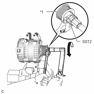
| *1 | Generator Pulley |
| *a | Hold |
| *b | Turn |
Tighten the generator pulley nut by turning SST1-A in the direction shown in the illustration.
- Torque:
- 133 N*m (1356 kgf*cm, 98 ft.*lbf)
Remove SST2 from the generator assembly.
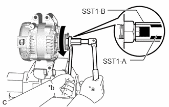
| *a | Hold |
| *b | Turn |
Turn SST1-B in the direction shown in the illustration and remove SST1-A and SST1-B.
Turn the generator pulley and check that the generator pulley moves smoothly.