M20D-FKS STARTING STARTER REASSEMBLY
PROCEDURE

 28021
1.INSTALL STARTER CENTER BEARING CLUTCH SUB-ASSEMBLY
28021
1.INSTALL STARTER CENTER BEARING CLUTCH SUB-ASSEMBLY
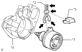
| *1 | Starter Center Bearing Clutch Sub-assembly |
| *2 | Pinion Drive Lever |
| *3 | Rubber Seal |
| *4 | Starter Drive Housing Assembly |

|
High-temperature Grease |
Apply high-temperature grease to the pinion drive lever as shown in the illustration.
Install the pinion drive lever and rubber seal to the starter center bearing clutch sub-assembly.
Install the starter center bearing clutch sub-assembly together with the pinion drive lever and rubber seal to the starter drive housing assembly.
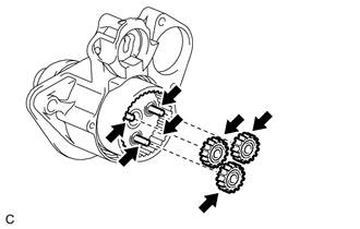
2.INSTALL PLANETARY GEAR
|
|
High-temperature Grease |
Apply high-temperature grease to the 3 planetary gears, 3 planetary gear shafts and starter center bearing clutch sub-assembly.
Install the 3 planetary gears to the starter center bearing clutch sub-assembly.
28160
3.INSTALL STARTER ARMATURE ASSEMBLY
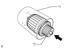
| *1 | Starter Yoke Assembly |
| *2 | Starter Armature Assembly |
Install the starter armature assembly to the starter yoke assembly.
- NOTICE:
-
The magnet of the starter yoke assembly may attract the starter armature assembly when the starter armature assembly is installed, causing the magnet to break.
28140
4.INSTALL STARTER BRUSH HOLDER ASSEMBLY
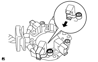
Hold the brush spring back and set the 4 brushes as shown in the illustration.
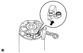
Install the starter brush holder assembly to the starter armature assembly and push in the 4 brushes as shown in the illustration.
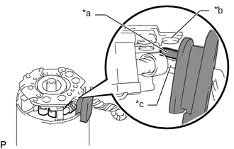
| *a | Grommet |
| *b | Negative (-) Brush Holder Plate |
| *c | Positive (+) Motor Lead Wire |
Fit the protrusion of the grommet between the negative (-) brush holder plate and positive (+) motor lead wire.
5.INSTALL STARTER COMMUTATOR END FRAME ASSEMBLY
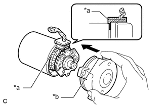
| *a | Lead Wire Rubber |
| *b | Cutout |
Install the starter commutator end frame assembly to the starter yoke assembly.
- NOTICE:
-
Align the lead wire rubber of the starter yoke assembly with the cutout of the starter commutator end frame assembly.
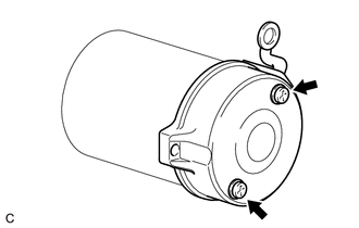
Install the 2 screws.
- Torque:
- 1.5 N*m (15 kgf*cm, 13 in.*lbf)
6.INSTALL STARTER ARMATURE PLATE
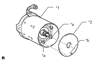
| *1 | Starter Yoke Assembly |
| *2 | Starter Armature Plate |
| *a | Stopper |
| *b | Protrusion |
Align the starter armature plate so that the protrusion fits between the stoppers of the starter yoke assembly, and install the starter armature plate.
- NOTICE:
-
Make sure the protrusion of the starter armature plate is inserted between the stoppers of the starter yoke assembly.
28120
7.INSTALL STARTER YOKE ASSEMBLY
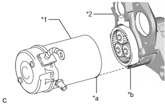
| *1 | Starter Yoke Assembly |
| *2 | Starter Drive Housing Assembly |
| *a | Cutout |
| *b | Protrusion |
Align the cutout of the starter yoke assembly with the protrusion of the starter drive housing assembly.
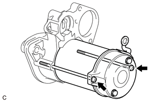
Using a T25 "TORX" socket wrench, install the 2 through bolts.
- Torque:
- 6.0 N*m (61 kgf*cm, 53 in.*lbf)
28150
8.INSTALL MAGNET STARTER SWITCH ASSEMBLY
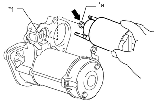
| *1 | Pinion Drive Lever |
| *a | Hook |
|
|
High-temperature Grease |
Apply high-temperature grease to the magnet starter switch assembly as shown in the illustration.
Hang the hook of the magnet starter switch assembly on the pinion drive lever.

Install the magnet starter switch assembly with the 2 nuts.
- Torque:
- 7.5 N*m (76 kgf*cm, 66 in.*lbf)
28249
9.INSTALL STARTER INRUSH CURRENT REDUCTION RELAY
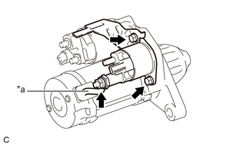
| *a | Lead Wire |
Install the starter inrush current reduction relay to the starter drive housing assembly with the 2 bolts.
- Torque:
- 7.9 N*m (81 kgf*cm, 70 in.*lbf)
Connect the lead wire to terminal M with the nut.
- Torque:
- 9.0 N*m (92 kgf*cm, 80 in.*lbf)
10.INSTALL WIRE HARNESS
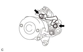
Install the wire harness to the starter assembly with the 2 nuts.
- Torque:
- 6.5 N*m (66 kgf*cm, 58 in.*lbf)
11.INSTALL HARNESS
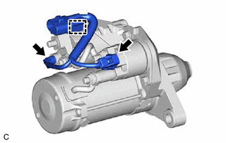
Engage the clamp and connect the 2 harness connectors to install the harness.