K121F CVT CONTINUOUSLY VARIABLE TRANSAXLE UNIT DISASSEMBLY
CAUTION / NOTICE / HINT
- NOTICE:
- ·
Clean the work area, tools to be used, other equipment, etc., thoroughly before performing this procedure, as there is a possibility that a CVT malfunction, which may prevent the vehicle from being driven, may occur if dust or fine foreign matter enters the CVT.
·Do not use cotton work gloves, cloths, paper towels, etc., that may produce lint, dust or foreign matter.
·When cleaning parts, make sure that dust or foreign matter does not enter the CVT.
·When replacing any tapered roller bearing (inner race) or tapered roller bearing (outer race), replace both the tapered roller bearing (inner race) and tapered roller bearing (outer race) with new ones.
·When the tapered roller bearing (inner race) is removed, the tapered roller bearing (inner race) and tapered roller bearing (outer race) need to be replaced.
·When the tapered roller bearing (inner race) is not removed, the tapered roller bearing (inner race) and tapered roller bearing (outer race) can be reused.
- HINT:
-
Shift shock may increase after replacing the transmission valve body assembly or forward multiple disc clutch assembly. In this case, shift shock will reduce as the vehicle in driven.
PROCEDURE

 32901L
1.REMOVE OIL COOLER ELBOW SUB-ASSEMBLY
32901L
1.REMOVE OIL COOLER ELBOW SUB-ASSEMBLY
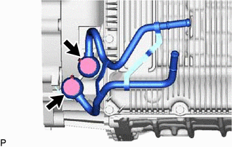
Remove the 2 bolts and oil cooler elbow sub-assembly from the continuously variable transaxle assembly.
Remove the 2 gaskets from the oil cooler elbow sub-assembly.
84540
2.REMOVE SHIFT LEVER POSITION SENSOR
89419B
3.REMOVE SHIFT STROKE SENSOR
89413M
4.REMOVE TRANSMISSION REVOLUTION SENSOR (NOUT)
89413N
5.REMOVE TRANSMISSION REVOLUTION SENSOR (NT)
89413T
6.REMOVE TRANSMISSION REVOLUTION SENSOR (NSS)
89637K
7.REMOVE OIL PRESSURE SENSOR
8.REMOVE REFILL PLUG
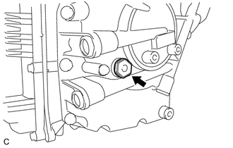
Remove the refill plug and gasket from the rear transaxle case sub-assembly.
30400
9.SUPPORT CONTINUOUSLY VARIABLE TRANSAXLE ASSEMBLY
Place the continuously variable transaxle assembly on wooden blocks.
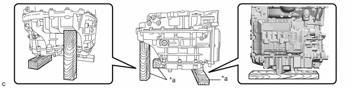
| *a | Wooden Block | - | - |
35125F
10.REMOVE OVERFLOW PLUG
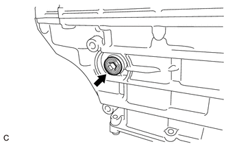
Using a 10 mm hexagon socket wrench, remove the overflow plug and gasket from the transaxle case sub-assembly.
35125E
11.REMOVE OVERFLOW (CVT) TUBE
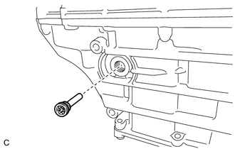
Using a 6 mm hexagon socket wrench, remove the overflow (CVT) tube from the transaxle case sub-assembly.
35015Y
12.REMOVE TRANSAXLE SIDE COVER SUB-ASSEMBLY
35410J
13.REMOVE TRANSMISSION VALVE BODY ASSEMBLY
82125M
14.REMOVE TRANSMISSION WIRE
89413S
15.REMOVE TRANSMISSION REVOLUTION SENSOR (NC1)
35111C
16.REMOVE TRANSAXLE HOUSING
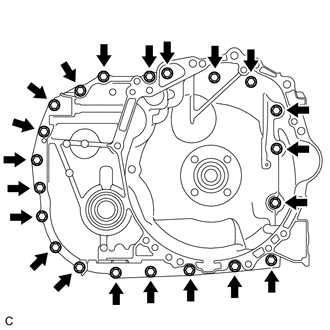
Remove the 21 bolts.
Using a plastic-faced hammer, tap on the circumference of the transaxle housing to remove it from the transaxle case sub-assembly.
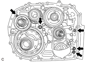
Remove the 5 O-rings from the transaxle case sub-assembly.
17.REMOVE SOLENOID OIL STRAINER
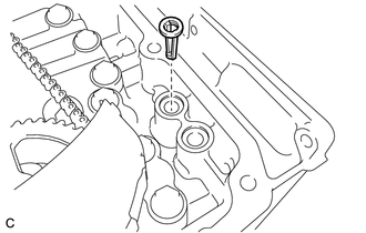
Remove the solenoid oil strainer from the transaxle case sub-assembly.
35174B
18.REMOVE OIL RESERVOIR LOCK PLATE
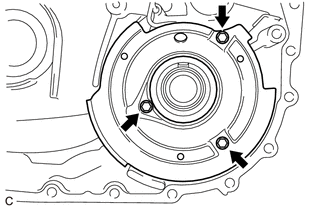
Remove the 3 bolts and oil reservoir lock plate from the transaxle housing.
35394D
19.REMOVE OIL CLEANER (CVT) MAGNET
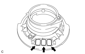
Remove the 3 oil cleaner (CVT) magnets from the oil reservoir lock plate.
35882E
20.REMOVE DIFFERENTIAL GEAR LUBE APPLY TUBE
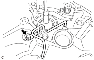
Remove the bolt and differential gear lube apply tube from the transaxle housing.
35896A
21.REMOVE SECONDARY SHAFT LUBE APPLY TUBE
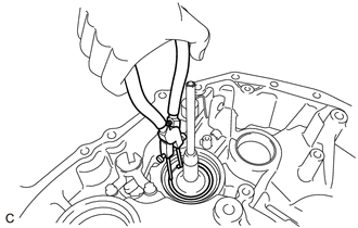
Using a snap ring plier, remove the snap ring from the transaxle housing.
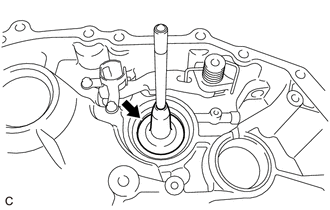
Remove the secondary shaft lube apply tube from the transaxle housing.
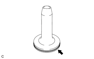
Remove the O-ring from the secondary shaft lube apply tube.
35809
22.REMOVE C-2 CLUTCH PRESSURE APPLY TUBE SUB-ASSEMBLY
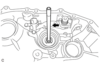
Remove the C-2 clutch pressure apply tube sub-assembly from the transaxle housing.
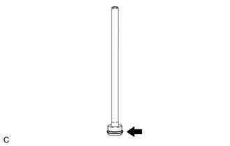
Remove the O-ring from the C-2 clutch pressure apply tube sub-assembly.
35593A
23.REMOVE CAM GUIDE SLEEVE
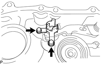
Remove the 2 bolts and cam guide sleeve from the transaxle housing.
35556N
24.REMOVE PARKING LOCK PAWL SHAFT
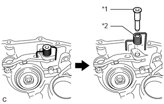
| *1 | Parking Lock Pawl Shaft |
| *2 | Torsion Spring |
Remove the parking lock pawl shaft and torsion spring from the transaxle housing.
35557C
25.REMOVE PARKING LOCK PAWL
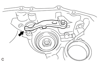
Remove the parking lock pawl from the transaxle housing.
35598B
26.REMOVE PARKING LOCK SLEEVE
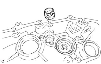
Remove the parking lock sleeve from the transaxle housing.
27.REMOVE REDUCTION DRIVEN GEAR FRONT TAPERED ROLLER BEARING (OUTER RACE)
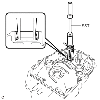
Using SST, remove the reduction driven gear front tapered roller bearing (outer race) and shim from the transaxle housing.
- SST
- 09308-00010
- NOTICE:
-
Be careful not to damage the transaxle housing.
- HINT:
-
-
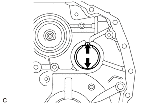
Align the claw of SST with the indentation of the transaxle housing when removing the parts.
28.REMOVE DIFFERENTIAL CASE FRONT TAPERED ROLLER BEARING (OUTER RACE)
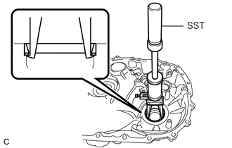
Using SST, remove the differential case front tapered roller bearing (outer race) and shim from the transaxle housing.
- SST
- 09308-00010
- NOTICE:
-
Be careful not to damage the transaxle housing.
- HINT:
-
-
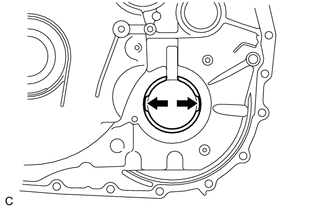
Align the claw of SST with the indentation of the transaxle housing when removing the parts.
41110G
29.REMOVE DIFFERENTIAL SIDE OIL SEAL
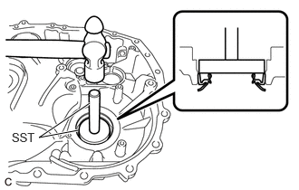
Using SST and a hammer, remove the differential side oil seal from the transaxle housing.
- SST
- 09950-70010 (09951-07100)
09950-60021 (09951-00730)
30.REMOVE TRANSAXLE HOUSING TYPE T OIL SEAL
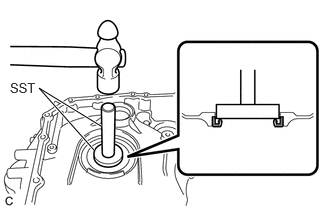
Using SST and a hammer, remove the transaxle housing type T oil seal from the transaxle housing.
- SST
- 09950-70010 (09951-07100)
09950-60011 (09951-00510)
31.REMOVE REDUCTION DRIVEN GEAR
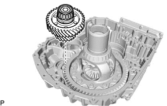
Remove the reduction driven gear from the transaxle case sub-assembly.
41301L
32.REMOVE FRONT DIFFERENTIAL CASE SUB-ASSEMBLY
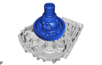
Remove the differential case sub-assembly from the transaxle case sub-assembly.
35317A
33.REMOVE NO. 2 TRANSMISSION OIL PUMP SEPARATOR PLATE
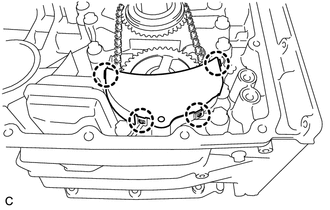
Detach the 4 claws to remove the No. 2 transmission oil pump separator plate from the No. 1 transmission oil pump separator plate.
35782P
34.REMOVE DRIVE SPROCKET
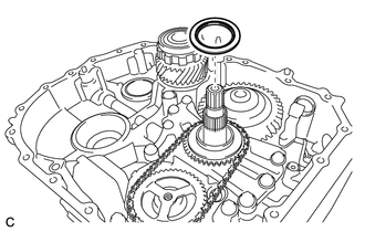
Remove the thrust needle roller bearing from the drive sprocket.
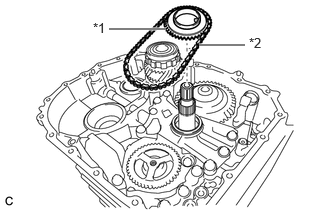
| *1 | Drive Sprocket |
| *2 | Transmission Drive Chain |
Remove the drive sprocket and transmission drive chain.
35783N
35.REMOVE DRIVEN SPROCKET
Using a snap ring expander, remove the driven sprocket from the front oil pump assembly.
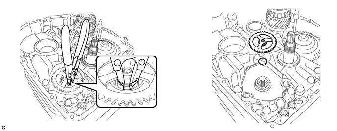
Remove the snap ring from the front oil pump assembly.
35316A
36.REMOVE NO. 1 TRANSMISSION OIL PUMP SEPARATOR PLATE
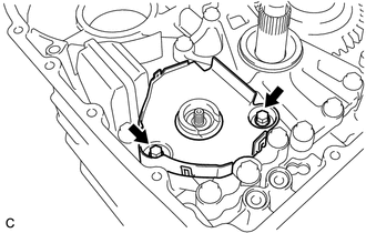
Remove the 2 bolts and No. 1 transmission oil pump separator plate from the front oil pump assembly.
35310A
37.REMOVE FRONT OIL PUMP ASSEMBLY
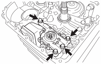
Remove the 4 bolts and front oil pump assembly from the transaxle case sub-assembly.
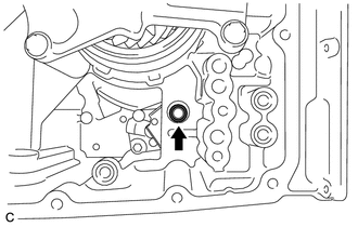
Remove the front oil pump cover gasket from the transaxle case sub-assembly.
35330J
38.REMOVE OIL STRAINER ASSEMBLY
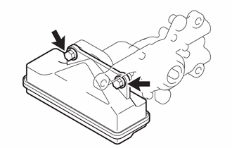
Remove the 2 bolts and oil strainer assembly from the front oil pump assembly.
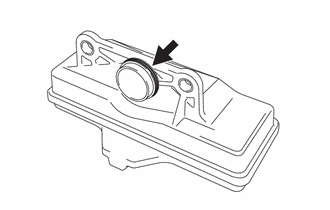
Remove the O-ring from the oil strainer assembly.
35016E
39.REMOVE TRANSMISSION CASE PLATE SUB-ASSEMBLY
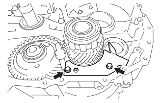
Remove the 2 bolts and transmission case plate sub-assembly from the transaxle case sub-assembly.
35174B
40.REMOVE OIL RESERVOIR LOCK PLATE
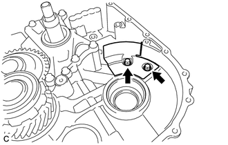
Remove the 2 bolts and oil reservoir lock plate from the transaxle case sub-assembly.
35370E
41.REMOVE STATOR (CVT) SHAFT ASSEMBLY
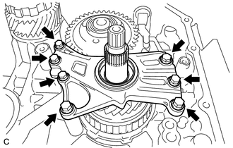
Remove the 7 bolts and stator (CVT) shaft assembly from the transaxle case sub-assembly.
33032
42.REMOVE 1ST GEAR SUB-ASSEMBLY
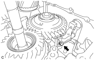
Remove the bolt to disconnect the No. 1 gear shift fork assembly from the No. 1 gear shift fork shaft.
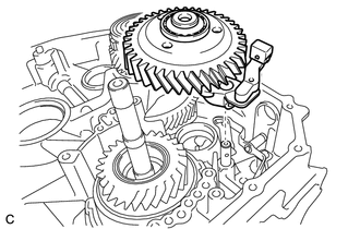
Remove the 1st gear sub-assembly with the No. 1 gear shift fork assembly from the No. 1 gear shift fork shaft.
33210A
43.REMOVE GEAR SHIFT FORK ASSEMBLY NO.1
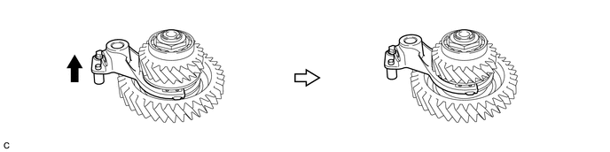
Move the No. 1 gear shift fork assembly as shown in the illustration.
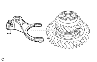
Remove the No. 1 gear shift fork assembly from the 1st gear sub-assembly.
44.REMOVE STAY
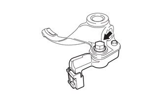
Remove the bolt and stay from the No. 1 gear shift fork assembly.
35610A
45.REMOVE FORWARD MULTIPLE DISC CLUTCH ASSEMBLY
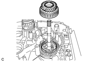
Remove the forward multiple disc clutch assembly from the planetary gear assembly.
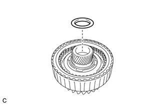
Remove the thrust bearing race from the forward multiple disc clutch assembly.
35633H
46.REMOVE FORWARD MULTIPLE DISC CLUTCH CLUTCH DISC
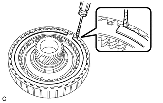
Using a screwdriver with its tip wrapped with protective tape, remove the snap ring from the forward clutch drum sub-assembly.
- NOTICE:
-
Be careful not to damage the forward clutch drum sub-assembly.
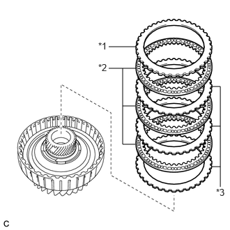
| *1 | Forward Clutch Flange |
| *2 | Forward Multiple Disc Clutch Clutch Disc |
| *3 | Forward Multiple Disc Clutch Clutch Plate |
Remove the forward clutch flange, 3 forward multiple disc clutch clutch discs and 3 forward multiple disc clutch clutch plates from the forward clutch drum sub-assembly.
47.REMOVE NO. 1 CLUTCH BALANCER
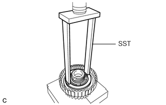
Place SST on the No. 1 clutch balancer and compress the forward clutch return spring sub-assembly with a press.
- SST
- 09387-00020
- NOTICE:
-
Do not compress the forward clutch return spring sub-assembly excessively.
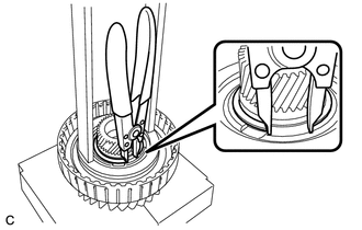
Using a snap ring expander, remove the snap ring from the forward clutch drum sub-assembly.
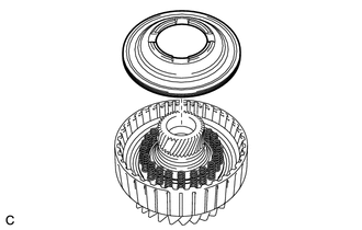
Remove the No. 1 clutch balancer from the forward clutch drum sub-assembly.
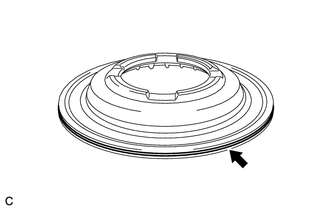
Remove the D-ring from the No. 1 clutch balancer.
35603E
48.REMOVE FORWARD CLUTCH RETURN SPRING SUB-ASSEMBLY
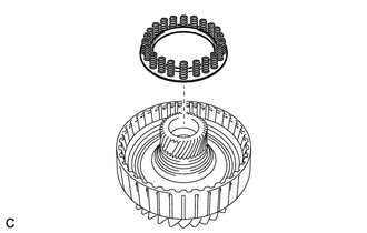
Remove the forward clutch return spring sub-assembly from the forward clutch drum sub-assembly.
49.REMOVE FORWARD CLUTCH PISTON
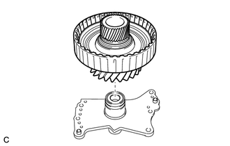
Install the forward clutch drum sub-assembly to the stator (CVT) shaft assembly.
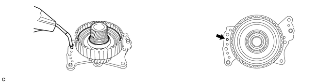
Apply compressed air (approximately 250 kPa (2.5 kgf/cm2, 36 psi)) to the fluid hole of the stator (CVT) shaft assembly to separate the forward clutch piston from the forward clutch drum sub-assembly.
- NOTICE:
-
Be careful as fluid may spray when applying compressed air.
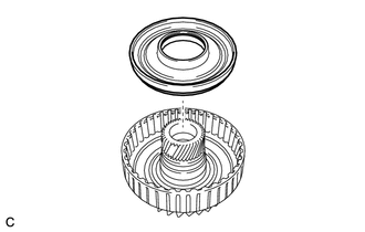
Remove the forward clutch piston from the forward clutch drum sub-assembly.
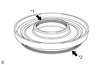
| *1 | O-Ring |
| *2 | D-Ring |
Remove the O-ring and D-ring from the forward clutch piston.
Remove the forward clutch drum sub-assembly from the stator (CVT) shaft assembly.
50.REMOVE CLUTCH DRUM OIL SEAL RING
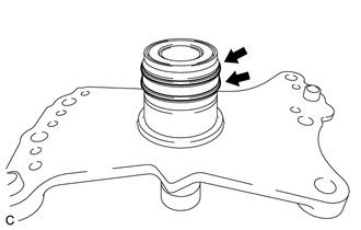
Remove the 2 clutch drum oil seal rings from the stator (CVT) shaft assembly.
- NOTICE:
-
Do not expand the clutch drum oil seal rings excessively.
35720M
51.REMOVE PLANETARY GEAR ASSEMBLY
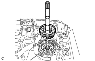
Remove the planetary gear assembly from the front planetary ring gear sub-assembly.
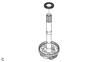
Remove the thrust needle roller bearing from the planetary gear assembly.
35075D
52.REMOVE FRONT PLANETARY RING GEAR SUB-ASSEMBLY
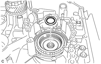
Remove the thrust needle roller bearing from the front planetary ring gear sub-assembly.
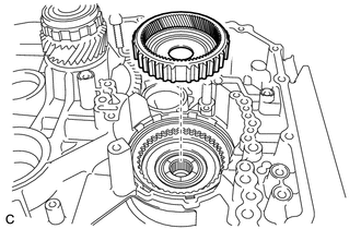
Remove the front planetary ring gear sub-assembly from the transaxle case sub-assembly.
35726A
53.REMOVE PLANETARY RING GEAR THRUST WASHER
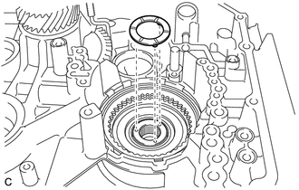
Remove the planetary ring gear thrust washer from the transaxle case sub-assembly.
35681B
54.REMOVE NO. 1 BRAKE DISC
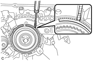
Using a screwdriver with its tip wrapped with protective tape, remove the snap ring from the transaxle case sub-assembly.
- NOTICE:
-
Be careful not to damage the transaxle case sub-assembly.
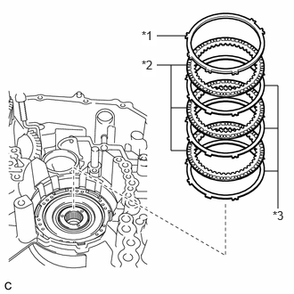
| *1 | Brake Flange |
| *2 | No. 1 Brake Disc |
| *3 | No. 1 Brake Plate |
Remove the brake flange, 3 No. 1 brake discs and 3 No. 1 brake plates from the transaxle case sub-assembly.
55.REMOVE 1ST AND REVERSE BRAKE RETURN SPRING SUB-ASSEMBLY
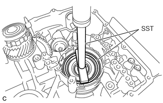
Place SST on the 1st and reverse brake return spring sub-assembly and compress it with a press.
- SST
- 09350-32014 (09351-32040)
09950-70010 (09951-07200)
- NOTICE:
-
Do not compress the 1st and reverse brake return spring sub-assembly excessively.
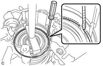
Using a screwdriver with its tip wrapped with protective tape, remove the snap ring from the transaxle case sub-assembly.
- NOTICE:
-
Be careful not to damage the transaxle case sub-assembly.
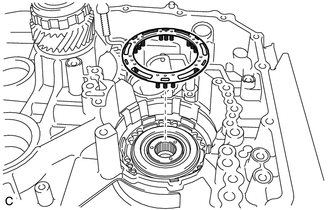
Remove the 1st and reverse brake return spring sub-assembly from the transaxle case sub-assembly.
35623L
56.REMOVE REVERSE BRAKE PISTON
Apply compressed air (approximately 250 kPa (2.5 kgf/cm2, 36 psi)) to the fluid hole to disconnect the reverse brake piston from the transaxle case sub-assembly.
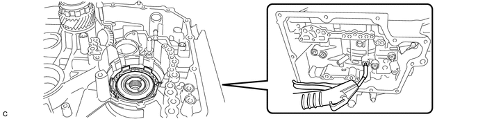
- NOTICE:
-
Be careful as fluid may spray when applying compressed air.
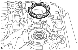
Remove the reverse brake piston from the transaxle case sub-assembly.
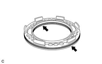
Remove the 2 O-rings from the reverse brake piston.
57.REMOVE REDUCTION DRIVEN GEAR REAR TAPERED ROLLER BEARING (OUTER RACE)
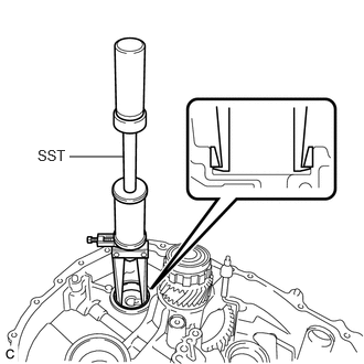
Using SST, remove the reduction driven gear rear tapered roller bearing (outer race) from the transaxle case sub-assembly.
- SST
- 09308-00010
- HINT:
-
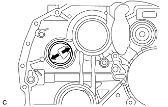
-
Align the claw of SST with the indentation of the transaxle case sub-assembly when removing the parts.
58.REMOVE DIFFERENTIAL CASE REAR TAPERED ROLLER BEARING (OUTER RACE)
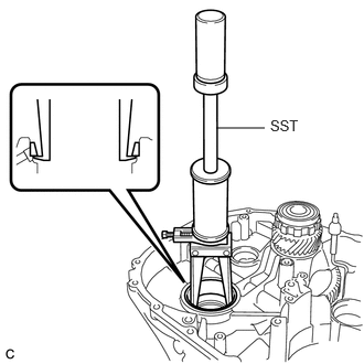
Using SST, remove the differential case rear tapered roller bearing (outer race) from the transaxle case sub-assembly.
- SST
- 09308-00010
- HINT:
-
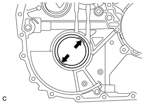
-
Align the claw of SST with the indentation of the transaxle case sub-assembly when removing the parts.
43420H
59.REMOVE FRONT DRIVE SHAFT OIL SEAL LH
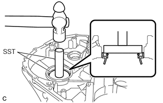
Using SST and a hammer, remove the front drive shaft oil seal LH from the transaxle case sub-assembly.
- SST
- 09950-60011 (09951-00650)
09950-70010 (09951-07100)
60.REMOVE REDUCTION DRIVEN GEAR REAR TAPERED ROLLER BEARING (INNER RACE)
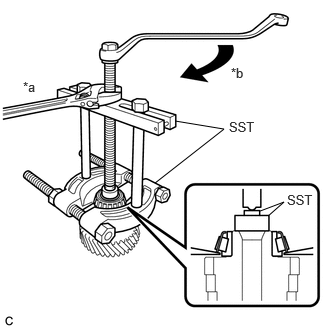
| *a | Hold |
| *b | Turn |
Using SST, remove the reduction driven gear rear tapered roller bearing (inner race) from the reduction driven gear.
- SST
- 09950-00020
09950-00030
09950-40011 (09957-04010)
09950-60011 (09951-00250)
- NOTICE:
-
Because SST is attached to the roller portion, there is a possibility that the roller portion could break and SST could come off before the reduction driven gear rear tapered roller bearing (inner race) comes off.
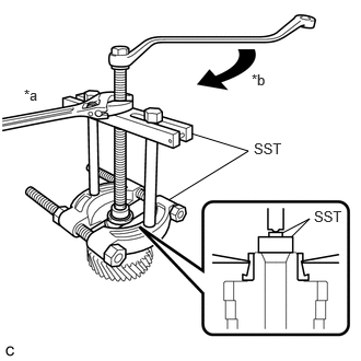
| *a | Hold |
| *b | Turn |
If the roller portion breaks and SST comes off, reattach SST to the inner race in the position shown in the illustration, and continue removing the parts.
- SST
- 09950-00020
09950-00030
09950-40011 (09957-04010)
09950-60011 (09951-00250)
61.REMOVE REDUCTION DRIVEN GEAR FRONT TAPERED ROLLER BEARING (INNER RACE)
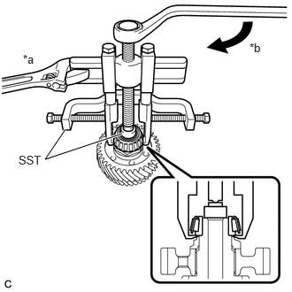
| *a | Hold |
| *b | Turn |
Using SST, remove the reduction driven gear front tapered roller bearing (inner race) from the reduction driven gear.
- SST
- 09950-40011 (09951-04010, 09952-04010, 09953-04020, 09954-04010, 09955-04061, 09957-04010, 09958-04011)
09950-60011 (09951-00210)
62.REMOVE DIFFERENTIAL CASE REAR TAPERED ROLLER BEARING (INNER RACE)
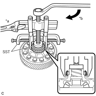
| *a | Hold |
| *b | Turn |
Using SST, remove the differential case rear tapered roller bearing (inner race) from the differential case sub-assembly.
- SST
- 09950-40011 (09951-04010, 09952-04010, 09953-04020, 09954-04010, 09955-04061, 09957-04010, 09958-04011)
09950-60011 (09951-00460)
63.REMOVE DIFFERENTIAL CASE FRONT TAPERED ROLLER BEARING (INNER RACE)
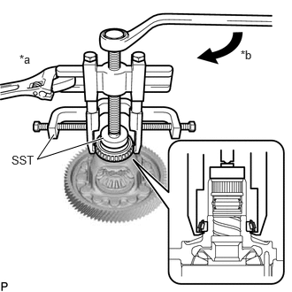
| *a | Hold |
| *b | Turn |
Using SST, remove the differential case front tapered roller bearing (inner race) from the differential case sub-assembly.
- SST
- 09950-40011 (09951-04010, 09952-04010, 09953-04020, 09954-04010, 09955-04061, 09957-04010, 09958-04011)
09950-60011 (09951-00530)
64.REMOVE STRAIGHT PIN
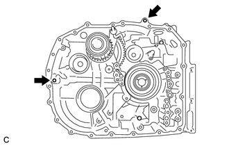
Remove the 2 straight pins from the transaxle case sub-assembly.