M20D-FKS INTAKE / EXHAUST EXHAUST MANIFOLD REMOVAL
CAUTION / NOTICE / HINT
The necessary procedures (adjustment, calibration, initialization or registration) that must be performed after parts are removed and installed, or replaced during exhaust manifold removal/installation are shown below.
| Replaced Part or Performed Procedure | Necessary Procedure | Effect/Inoperative Function when Necessary Procedure not Performed | Link |
|---|---|---|---|
| Front exhaust pipe assembly | GPF deposition value clear | ·
MIL comes on ·
Deterioration of fuel efficiency |
( 202304,202409,_51,_083058,_0401834,RM1000000029C6V,202409,999999,_51,_083058,_0401834,RM100000002NA8M,) 202304,202409,_51,_083058,_0401834,RM1000000029C6V,202409,999999,_51,_083058,_0401834,RM100000002NA8M,)
|
·
Replacement of air fuel ratio sensor ·
Gas leak from exhaust system is repaired |
Inspection After Repair | ·
Poor idle, etc. ·
Engine start function, etc. |
(202304,202409,_51,_083058,_0401834,RM1000000029C6V,202409,999999,_51,_083058,_0401834,RM100000002NA8M,)
|
| Exhaust manifold | Total Short Trip Estimate | ·
MIL comes on ·
Deterioration of fuel efficiency |
(202304,202409,_51,_083058,_0401834,RM1000000029C6V,202409,999999,_51,_083058,_0401834,RM100000002NA8M,)
|
- CAUTION:
- ·
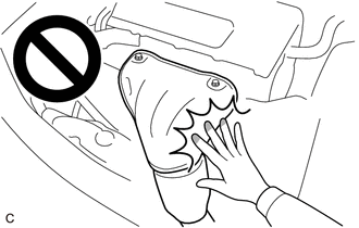
To prevent burns, do not touch the engine, exhaust manifold or other high temperature components while the engine is hot.
·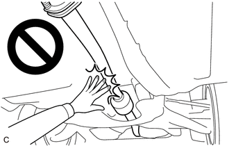
To prevent burns, do not touch the engine, exhaust pipe or other high temperature components while the engine is hot.
PROCEDURE

 51420
1.REMOVE NO. 2 ENGINE UNDER COVER ASSEMBLY
51420
1.REMOVE NO. 2 ENGINE UNDER COVER ASSEMBLY
17410
2.REMOVE FRONT EXHAUST PIPE ASSEMBLY
- CAUTION:
-
To prevent burns, do not touch the engine, exhaust pipe or other high temperature components while the engine is hot.
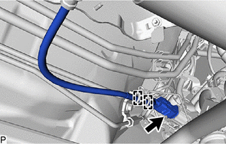
Detach the 2 wire harness clamps.
Disconnect the air fuel ratio sensor (for Sensor 2) connector.
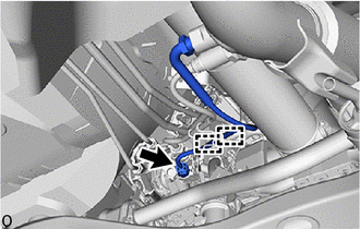
Detach the 2 clamps.
Disconnect the exhaust gas temperature sensor connector.
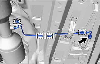
Detach the 4 clamps.
Disconnect the No. 2 exhaust gas temperature sensor connector.
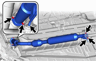
Remove the 2 bolts, 2 nuts and disconnect the front exhaust pipe assembly from the exhaust manifold and tail exhaust pipe assembly.
Remove the front exhaust pipe assembly from the 2 exhaust pipe supports.
Remove the 2 gaskets from the front exhaust pipe assembly.
89467B
3.REMOVE AIR FUEL RATIO SENSOR (for Sensor 1)
4.REMOVE WIRE HARNESS CLAMP BRACKET
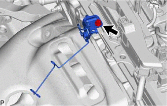
Remove the bolt and wire harness clamp bracket.
25760
5.REMOVE VACUUM TRANSMITTING HOSE ASSEMBLY
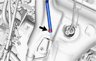
Slide the clip and remove the vacuum transmitting hose assembly from the No. 1 vacuum transmitting pipe sub-assembly.
25706
6.REMOVE NO. 1 VACUUM TRANSMITTING PIPE SUB-ASSEMBLY
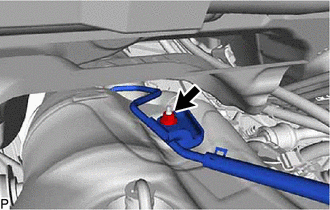
Remove the nut and disconnect the No. 1 vacuum transmitting pipe sub-assembly from the exhaust manifold.

Using a 14 mm union nut wrench, remove the No. 1 vacuum transmitting pipe sub-assembly from the exhaust manifold.
17167
7.SEPARATE NO. 1 EXHAUST MANIFOLD HEAT INSULATOR
- CAUTION:
-
To prevent burns, do not touch the engine, exhaust manifold or other high temperature components while the engine is hot.
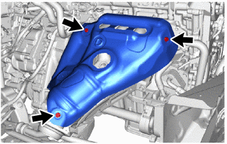
Remove the 3 bolts and separate the No. 1 exhaust manifold heat insulator from the exhaust manifold.
58151
8.SEPARATE NO. 1 UPPER FRONT FLOOR HEAT INSULATOR
- CAUTION:
-
To prevent burns, do not touch the engine, exhaust manifold or other high temperature components while the engine is hot.
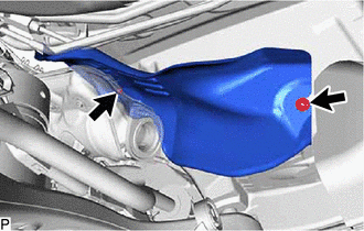
Remove the 2 nuts and separate the No. 1 upper front floor heat insulator from the vehicle body.
17118
9.REMOVE MANIFOLD STAY
- CAUTION:
-
To prevent burns, do not touch the engine, exhaust manifold or other high temperature components while the engine is hot.
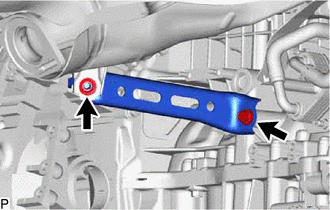
Remove the bolt, nut and manifold stay from the exhaust manifold and cylinder block sub-assembly.
17141
10.REMOVE EXHAUST MANIFOLD
- CAUTION:
-
To prevent burns, do not touch the engine, exhaust manifold or other high temperature components while the engine is hot.
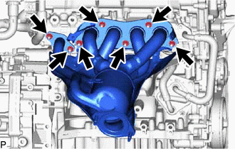
Using a 12 mm deep socket wrench, remove the 7 nuts and separate the exhaust manifold from the cylinder head sub-assembly.
Remove the No. 1 exhaust manifold heat insulator, No. 1 upper front floor heat insulator and exhaust manifold.
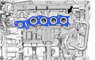
Remove the exhaust manifold to head gasket from the cylinder head sub-assembly.
17168
11.REMOVE NO. 2 EXHAUST MANIFOLD HEAT INSULATOR
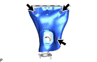
Remove the 3 bolts and No. 2 exhaust manifold heat insulator from the exhaust manifold.