K121 CVT VALVE BODY ASSEMBLY INSPECTION
CAUTION / NOTICE / HINT
- HINT:
-
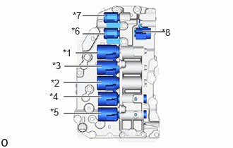 1.219,0.229 1.552,0.229 true 2.104,0.469 2.438,0.469 true 1.219,0.5 1.552,0.5 true 1.115,0.781 1.448,0.781 true 0.938,1.219 1.49,1.219 true 0.948,0.979 1.5,0.979 true 0.938,1.427 1.49,1.427 true 0.938,1.677 1.49,1.677 true 0.927,0.698 1.24,0.854 0.313,0.156 10 false *1 0.75,1.146 1.063,1.302 0.313,0.156 10 false *2 0.771,0.885 1.083,1.042 0.313,0.156 10 false *3 0.729,1.344 1.042,1.5 0.313,0.156 10 false *4 0.74,1.573 1.052,1.729 0.313,0.156 10 false *5 1.052,0.375 1.365,0.531 0.313,0.156 10 false *6 1.073,0.146 1.385,0.302 0.313,0.156 10 false *7 2.385,0.396 2.698,0.552 0.313,0.156 10 false *8
*1 Shift Solenoid Valve SL1 *2 Shift Solenoid Valve SL2 *3 Shift Solenoid Valve SLU *4 Shift Solenoid Valve SLP *5 Shift Solenoid Valve SLS *6 Shift Solenoid Valve SC1 *7 Shift Solenoid Valve SC2 *8 Shift Solenoid Valve SC3
-
Solenoid valve position
PROCEDURE

 1.INSPECT TRANSMISSION VALVE BODY ASSEMBLY
Inspect Shift Solenoid Valve SL1:
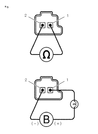
| *a | Component without harness connected
(Shift Solenoid Valve SL1) |
Measure the resistance according to the value(s) in the table below.
- Standard Resistance:
Tester Connection Condition Specified Condition 1 - 2 20°C (68°F) 5.0 to 5.6 Ω
If the result is not as specified, replace the transmission valve body assembly.
Connect a positive (+) lead from the battery with a 21 W bulb to terminal 1 and a negative (-) lead to terminal 2 of the shift solenoid valve SL1 connector, and check that the shift solenoid valve SL1 moves and makes an operating sound.
- NOTICE:
-
When using battery voltage during the inspection, do not bring the positive (+) and negative (-) tester probes too close to each other as a short circuit may occur.
- OK:
The shift solenoid valve SL1 moves and makes an operating sound.
If the result is not as specified, replace the transmission valve body assembly.
Inspect Shift Solenoid Valve SL2:
- HINT:
-
Refer to Inspect Shift Solenoid Valve SL1
Inspect Shift Solenoid Valve SLU:
- HINT:
-
Refer to Inspect Shift Solenoid Valve SL1
Inspect Shift Solenoid Valve SLP:
- HINT:
-
Refer to Inspect Shift Solenoid Valve SL1
Inspect Shift Solenoid Valve SLS:
- HINT:
-
Refer to Inspect Shift Solenoid Valve SL1
Inspect Shift Solenoid Valve SC1:
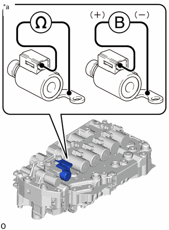
| *a | Component without harness connected
(Shift Solenoid Valve SC1) |
Measure the resistance according to the value(s) in the table below.
- Standard Resistance:
Tester Connection Condition Specified Condition Shift Solenoid Valve SC1 connector terminal- Shift Solenoid Valve SC1 body 20°C 11 to 15 Ω
Inspect Shift Solenoid Valve SC2:
- HINT:
-
Refer to Inspect Shift Solenoid Valve SC1.
Inspect Shift Solenoid Valve SC3:
- HINT:
-
Refer to Inspect Shift Solenoid Valve SC1.