K121 CVT OIL COOLER INSTALLATION
PROCEDURE

 33493C
1.INSTALL TRANSMISSION OIL COOLER
33493C
1.INSTALL TRANSMISSION OIL COOLER
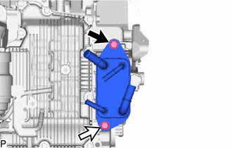

|
Bolt A |

|
Bolt B |
Install the transmission oil cooler to the continuously variable transaxle assembly with the 2 bolts.
- Torque:
- 13.5 N*m (138 kgf*cm, 10 ft.*lbf)
- HINT:
-
Tightening order: Temporarily install bolt (A) → Tighten bolt (B) → Tighten bolt (A)
32941R
2.CONNECT OIL COOLER INLET HOSE
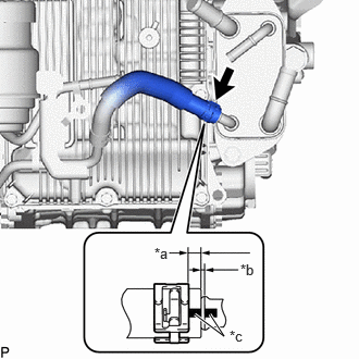
| *a | 2 to 7 mm (0.0787 to 0.275 in.) |
| *b | 0 to 3 mm (0 to 0.118 in.) |
| *c | Paint Mark |
Connect the oil cooler inlet hose to the transmission oil cooler, and slide the hose clip to secure the hose.
- NOTICE:
- ·
Make sure to slide the oil cooler inlet hose until it contacts the hose stopper of the transmission oil cooler.
·Make sure to align the paint mark of the oil cooler inlet hose with the paint mark of the transmission oil cooler.
·Make sure that the claws of the hose clip are within the location shown in the illustration.
32942N
3.CONNECT NO. 1 OIL COOLER OUTLET HOSE
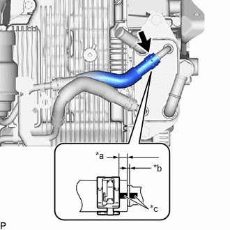
| *a | 2 to 7 mm (0.0787 to 0.275 in.) |
| *b | 0 to 3 mm (0 to 0.118 in.) |
| *c | Paint Mark |
Connect the No. 1 oil cooler outlet hose to the transmission oil cooler, and slide the hose clip to secure the hose.
- NOTICE:
- ·
Make sure to slide the No. 1 oil cooler outlet hose until it contacts the hose stopper of the transmission oil cooler.
·Make sure to align the paint mark of the No. 1 oil cooler outlet hose with the paint mark of the transmission oil cooler.
·Make sure that the claws of the hose clip are within the location shown in the illustration.
16264D
4.CONNECT NO. 2 WATER BY-PASS HOSE
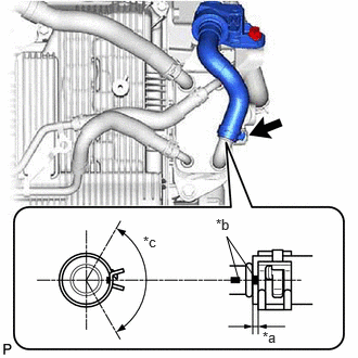
| *a | 2 to 7 mm (0.0787 to 0.275 in.) |
| *b | Paint Mark (LH Side of Vehicle) |
| *c | 120° (Claw of Hose Clip Location) |
Connect the No. 2 water by-pass hose to the transmission oil cooler and slide the hose clip to secure the hose.
- NOTICE:
- ·
Make sure to slide the No. 2 water by-pass hose until it contacts the hose stopper of the transmission oil cooler.
·Align the hose paint mark the position shown in the illustration.
·Make sure that the claws of the hose clip are within the location shown in the illustration.
16261G
5.CONNECT NO. 1 WATER BY-PASS HOSE
Connect the No. 1 water by-pass hose to the transmission oil cooler and slide the hose clip to secure the hose.
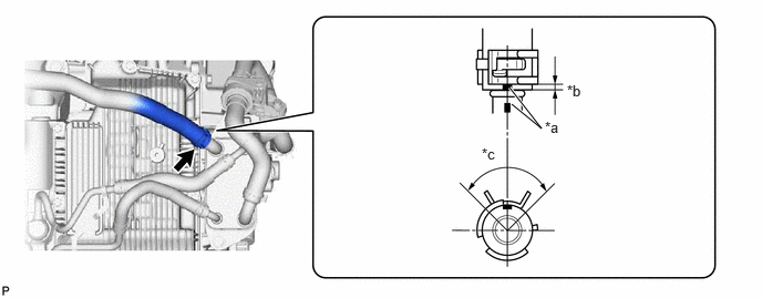
| *a | Paint Mark (Upper Side of Vehicle) | *b | 2 to 7 mm (0.0787 to 0.275 in.) |
| *c | 120° (Claw of Hose Clip Location) | - | - |
- NOTICE:
- ·
Make sure to slide the No. 1 water by-pass hose until it contacts the hose stopper of the transmission oil cooler.
·Make sure to align the paint mark of the No. 1 water by-pass hose with the paint mark of the transmission oil cooler.
·Make sure that the claws of the hose clip are within the location shown in the illustration.
6.ADD CONTINUOUSLY VARIABLE TRANSAXLE FLUID
7.INSPECT FOR CONTINUOUSLY VARIABLE TRANSAXLE FLUID LEAK
53737D
8.INSTALL FRONT FENDER APRON SEAL LH
51420
9.INSTALL NO. 2 ENGINE UNDER COVER ASSEMBLY
51441
10.INSTALL NO. 1 ENGINE UNDER COVER
53896B
11.INSTALL FRONT FENDER FRONT SPLASH SHIELD LH
53895B
12.INSTALL FRONT FENDER FRONT SPLASH SHIELD RH