RM36D0EC _51 Engine / Hybrid System _083056 STOP AND START _0402418 STOP AND START SYSTEM J

STOP AND START  STOP AND START SYSTEM  STA Signal Circuit  


DESCRIPTION

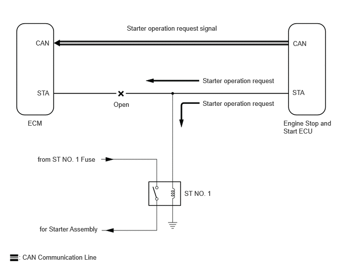
While the engine is being cranked, a starter operation request signal is sent to terminal STA of the ECM.

HINT:

If there is an open in the STA circuit of the ECM, stop and start control will be prohibited after the third time the engine is started by stop and start control.

·

Stop and start control will be prohibited until the ignition switch is turned off.

·

The MIL will not illuminate.

·

If there is an open in the STA circuit of the ECM, the engine can still be started using the ignition switch, as the ECM also receives the starter operation request signal from the engine stop and start ECU via CAN communication. (Stop and start control is prohibited as the reliability of the signal sent via CAN communication cannot be assured while the voltage drops during operation of the starter assembly.)


A347476E35
2.667,0.51 4.604,0.75 1.938,0.24 10 false Starter operation request signal 4.26,1.615 5.823,1.833 1.563,0.219 10 false Starter operation request 4.26,2.094 5.823,2.313 1.563,0.219 10 false Starter operation request 5.958,2.51 7.01,2.865 1.052,0.354 10 false Engine Stop and Start ECU 2.385,2.115 3,2.313 0.615,0.198 10 false Open 0.583,2.51 1.042,2.708 0.458,0.198 10 false ECM 0.781,1.875 1.24,2.073 0.458,0.198 10 false STA 6.156,0.833 6.615,1.031 0.458,0.198 10 false CAN 0.75,0.823 1.208,1.021 0.458,0.198 10 false CAN 0.833,4.74 3.896,4.938 3.063,0.198 10 false for Starter Assembly 0.396,5.333 2.156,5.552 1.76,0.219 10 false : CAN Communication Line 6.146,1.865 6.74,2.083 0.594,0.219 10 false STA 3.875,3.99 5.104,4.188 1.229,0.198 10 false ST NO. 1 0.792,3.271 3.542,3.469 2.75,0.198 10 false from ST NO. 1 Fuse

WIRING DIAGRAM

A538303E01
0.969,0.635 1.583,0.833 0.615,0.198 10 false CANH 0.979,1.104 1.594,1.302 0.615,0.198 10 false CANL 1.063,1.583 1.677,1.781 0.615,0.198 10 false STA 1.49,0.438 2.042,0.615 0.552,0.177 10 false 4*1 1.458,1.396 2.01,1.573 0.552,0.177 10 false 18*1 1.438,0.625 2.052,0.823 0.615,0.198 10 false A116 0.885,2.385 1.5,2.583 0.615,0.198 10 false ECM 5.896,0.625 6.51,0.823 0.615,0.198 10 false CANH 5.896,1.104 6.51,1.302 0.615,0.198 10 false CANL 5.896,1.583 6.51,1.781 0.615,0.198 10 false STA 5.521,1.115 5.948,1.281 0.427,0.167 10 false A32 5.51,1.583 5.938,1.75 0.427,0.167 10 false A34 5.552,0.448 5.979,0.615 0.427,0.167 10 false 13 5.542,0.917 5.969,1.083 0.427,0.167 10 false 14 5.563,1.365 5.99,1.531 0.427,0.167 10 false 21 3.198,4.281 3.813,4.479 0.615,0.198 10 false ST NO. 1 3.833,3.448 4.365,3.635 0.531,0.188 10 false 3 3.833,3.854 4.365,4.042 0.531,0.188 10 false 2 3.052,3.448 3.583,3.635 0.531,0.188 10 false 5 3.042,3.865 3.573,4.052 0.531,0.188 10 false 1 1.656,3.708 2.271,3.906 0.615,0.198 10 false ST NO. 1 0.885,4.698 1.5,4.896 0.615,0.198 10 false Battery 1.646,5.354 3.375,5.656 1.729,0.302 10 false : CAN Communication Line 5.677,4.26 6.802,4.563 1.125,0.302 10 false Starter Assembly 5.688,4.115 6.813,4.417 1.125,0.302 10 false C43 5.875,3.563 6.802,3.844 0.927,0.281 10 false SL1 5.708,3.448 5.99,3.635 0.281,0.188 10 false 2 5.427,2.385 7.125,2.688 1.698,0.302 10 false Engine Stop and Start ECU 5.521,0.646 5.948,0.813 0.427,0.167 10 false A32 1.885,1.396 2.438,1.573 0.552,0.177 10 false 18*2 3.583,4.979 5.823,5.188 2.24,0.208 10 false *1: SFTM Made 3.573,5.333 5.813,5.542 2.24,0.208 10 false *2: GTMC Made 1.448,1.583 2.063,1.781 0.615,0.198 10 false A116 1.865,1.583 2.479,1.781 0.615,0.198 10 false A125 1.448,1.115 2.063,1.313 0.615,0.198 10 false A116 1.875,1.115 2.49,1.313 0.615,0.198 10 false A125 1.865,0.625 2.479,0.823 0.615,0.198 10 false A125 1.5,0.917 2.052,1.094 0.552,0.177 10 false 5*1 1.917,0.438 2.469,0.615 0.552,0.177 10 false 4*2 1.938,0.917 2.49,1.094 0.552,0.177 10 false 5*2

PROCEDURE

1.READ VALUE USING GTS (STARTER SW)
a.

Connect the GTS to the DLC3.


b.

Turn the ignition switch to ON.


c.

Turn the GTS on.


d.

Enter the following menus: Powertrain / Engine / Data List / Starter SW.

Powertrain > Engine > Data List
Tester Display
Starter SW
50003 372 11

e.

Read the values displayed on the GTS when the ignition switch is ON and START.

OK:
GTS Display Condition Normal Condition
Starter SW Ignition switch ON OFF
Ignition switch START ON


Result:
Proceed to
OK
NG


OK

NG

2.CHECK HARNESS AND CONNECTOR (ECM - ST NO. 1 RELAY)
a.

Disconnect the ECM connector.


b.

Remove the ST NO. 1 relay from the No. 1 engine room relay block and No. 1 junction block assembly.


c.

Disconnect the engine stop and start ECU connector.


d.

Measure the resistance according to the value(s) in the table below.

Standard Resistance:
Tester Connection Condition Specified Condition
A116-18 (STA)*1 - ST NO. 1 relay terminal 2 Always Below 1 Ω
A125-18 (STA)*2 - ST NO. 1 relay terminal 2 Always Below 1 Ω


*1: SFTM Made

*2: GTMC Made


Result:
Proceed to
OK
NG


OK

NG

REPAIR OR REPLACE HARNESS OR CONNECTOR