M20D-FKS ENGINE CONTROL SFI SYSTEM P010012 Mass or Volume Air Flow Sensor "A" Circuit Short to Battery P010014 Mass or Volume Air Flow Sensor "A" Circuit Short to Ground or Open
DESCRIPTION
The mass air flow meter sub-assembly is a sensor that measures the intake air volume using the following built-in components:
By-pass duct (allows some of the intake air to flow past a silicon chip sensor)
Silicon chip sensor (uses a heater control bridge circuit and temperature sensor bridge circuit to detect the difference in the temperature of the intake air that passes the sensors positioned before and after the heater)
Control circuit (converts the difference in temperature into a pulse signal and performs correction)
Intake air flows past the temperature sensor (before heater), the heater, and then the temperature sensor (after heater) of the silicon chip sensor in the by-pass duct. As the intake air is warmed up when it is exposed to the heater, the temperature of the intake air as it flows past the temperature sensor (after heater) is higher than when it flows past the temperature sensor (before heater). The difference in temperature of the intake air at each temperature sensor varies depending on the velocity of the intake air that flows past the silicon chip sensor. The temperature sensor bridge circuit detects the difference in temperature and the control circuit converts it into a pulse signal and outputs it to the ECM. When the temperature detected by the temperature sensor (before heater) is higher than that detected by the temperature sensor (after heater), backflow of the intake air is detected.
The ECM calculates the intake air volume based on the pulse signal received from the mass air flow meter sub-assembly, and uses it to determine the fuel injection duration necessary for an optimal air-fuel ratio.
The heater control bridge circuit has a temperature sensor and power transistor, and maintains the heater temperature at a specific temperature.
- HINT:
-
When DTCs are stored, the ECM enters fail-safe mode. During fail-safe mode, the ECM calculates the fuel injection duration based on the engine speed and throttle valve angle. Fail-safe mode continues until a pass condition is detected.
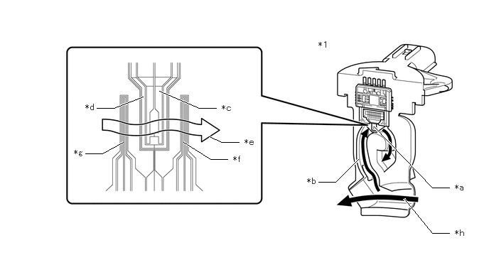
| *1 | Mass Air Flow Meter Sub-assembly | - | - |
| *a | Silicon Chip Sensor | *b | By-pass Duct |
| *c | Heater | *d | Heater Thermistor |
| *e | Intake Air | *f | Temperature Sensor (After Heater) |
| *g | Temperature Sensor (Before Heater) | *h | Air Flow |
| DTC No. | Detection Item | DTC Detection Condition | Trouble Area | MIL | Memory | Note |
|---|---|---|---|---|---|---|
| P010012 | Mass or Volume Air Flow Sensor "A" Circuit Short to Battery | The mass air flow meter sub-assembly output frequency is higher than 9.8 kHz for 3 seconds or more (1 trip detection logic). | ·
Open or short in mass air flow meter sub-assembly circuit ·
Mass air flow meter sub-assembly ·
ECM |
Comes on | DTC stored | SAE: P0103 |
| P010014 | Mass or Volume Air Flow Sensor "A" Circuit Short to Ground or Open | The mass air flow meter sub-assembly output frequency is less than 0.1 kHz for 3 seconds or more (1 trip detection logic). | ·
Open or short in mass air flow meter sub-assembly circuit ·
Mass air flow meter sub-assembly ·
ECM |
Comes on | DTC stored | SAE: P0102 |
MONITOR DESCRIPTION
If there is a defect or an open or short circuit in the mass air flow meter sub-assembly, the frequency level deviates from the normal operating range. The ECM interprets this deviation as a malfunction in the mass air flow meter sub-assembly circuit and stores a DTC.
Example:
When the sensor output frequency remains less than 0.1 kHz, or higher than 9.8 kHz for 3 seconds, the ECM stores a DTC.
MONITOR STRATEGY
| Frequency of Operation | Continuous |
CONFIRMATION DRIVING PATTERN
- HINT:
- ·
After repair has been completed, clear the DTC and then check that the vehicle has returned to normal by performing the following All Readiness check procedure.
·When clearing the permanent DTCs, refer to the "CLEAR PERMANENT DTC" procedure.
Connect the GTS to the DLC3.
Turn the ignition switch to ON.
Turn the GTS on.
Clear the DTCs (even if no DTCs are stored, perform the clear DTC procedure).
Turn the ignition switch off and wait for at least 30 seconds.
Turn the ignition switch to ON [A].
Turn the GTS on.
Wait 5 seconds or more [B].
Enter the following menus: Powertrain / Engine / Trouble Codes [C].
Read the pending DTCs.
- HINT:
- ·
If a pending DTC is output, the system is malfunctioning.
·If a pending DTC is not output, perform the following procedure.
Enter the following menus: Powertrain / Engine / Utility / All Readiness.
Input the DTC: P010012 or P010014.
Check the DTC judgment result.
| GTS Display | Description |
|---|---|
| NORMAL | ·
DTC judgment completed ·
System normal |
| ABNORMAL | ·
DTC judgment completed ·
System abnormal |
| INCOMPLETE | ·
DTC judgment not completed ·
Perform driving pattern after confirming DTC enabling conditions |
- HINT:
- ·
If the judgment result is NORMAL, the system is normal.
·If the judgment result is ABNORMAL, the system has a malfunction.
·[A] to [C]: Normal judgment procedure.
The normal judgment procedure is used to complete DTC judgment and also used when clearing permanent DTCs.
·When clearing the permanent DTCs, do not disconnect the cable from the battery terminal or attempt to clear the DTCs during this procedure, as doing so will clear the universal trip and normal judgment histories.
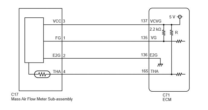
WIRING DIAGRAM
CAUTION / NOTICE / HINT
- HINT:
-
Read Freeze Frame Data using the GTS. The ECM records vehicle and driving condition information as Freeze Frame Data the moment a DTC is stored. When troubleshooting, Freeze Frame Data can help determine if the vehicle was moving or stationary, if the engine was warmed up or not, if the air fuel ratio was lean or rich, and other data from the time the malfunction occurred.
PROCEDURE
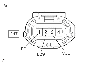
| *a | Front view of wire harness connector
(to Mass Air Flow Meter Sub-assembly) |
Disconnect the mass air flow meter sub-assembly connector.
Turn the ignition switch to ON.
Measure the voltage according to the value(s) in the table below.
- Standard Voltage:
Tester Connection Switch Condition Specified Condition C17-3 (VCC) - C17-2 (E2G) Ignition switch ON 4.5 to 5.5 V C17-1 (FG) - C17-2 (E2G) Ignition switch ON 4.5 to 5.5 V
Turn the ignition switch off and wait for at least 30 seconds.
Measure the resistance according to the value(s) in the table below.
- Standard Resistance:
Tester Connection Condition Specified Condition C17-3 (VCC) - C17-1 (FG) Ignition switch off 2.09 to 2.31 kΩ C17-2 (E2G) - Body ground Always Below 1 Ω
- Result:
Proceed to OK NG
OK
NG
Disconnect the mass air flow meter sub-assembly connector.
Disconnect the ECM connector.
Measure the resistance according to the value(s) in the table below.
- Standard Resistance:
Tester Connection Condition Specified Condition C17-3 (VCC) - C71-137 (VCVG) Always Below 1 Ω C17-1 (FG) - C71-135 (VG) Always Below 1 Ω C17-2 (E2G) - C71-136 (E2G) Always Below 1 Ω C17-3 (VCC) or C71-137 (VCVG) - Body ground and other terminals Always 10 kΩ or higher C17-1 (FG) or C71-135 (VG) - Body ground and other terminals Always 10 kΩ or higher C17-2 (E2G) or C71-136 (E2G) - Body ground and other terminals Always 10 kΩ or higher
- Result:
Proceed to OK NG
OK
NG