FRONT SUSPENSION FRONT STABILIZER BAR INSTALLATION
PROCEDURE

 48815
1.INSTALL FRONT NO. 1 STABILIZER BAR BUSHING (for LH Side)
48815
1.INSTALL FRONT NO. 1 STABILIZER BAR BUSHING (for LH Side)
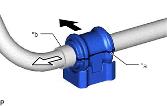
| *a | Cutout |
| *b | Stopper Ring |

|
Front of the Vehicle |

|
Outside of the Vehicle |
Install the front No. 1 stabilizer bar bushing to the front stabilizer bar as shown in the illustration.
- NOTICE:
- ·
Install the front No. 1 stabilizer bar bushing so that the cutout is facing the rear of the vehicle.
·Install the front No. 1 stabilizer bar bushing onto the front stabilizer bar so that the stopper ring of the front stabilizer bar faces the outside of the vehicle.
48815
2.INSTALL FRONT NO. 1 STABILIZER BAR BUSHING (for RH Side)
- HINT:
-
Perform the same procedure as for the LH side.
48811
3.INSTALL FRONT STABILIZER BAR
Install the front stabilizer bar with the 2 front stabilizer bar bushings to the front frame assembly.
- NOTICE:
-
Make sure that the identification mark is positioned as shown in the illustration.
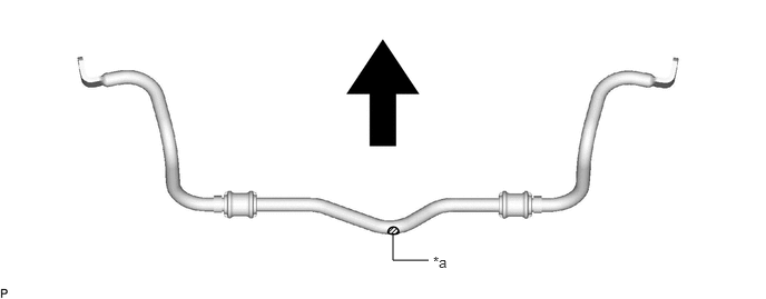
| *a | Identification Mark | - | - |
|
|
Front of the Vehicle | - | - |
48829A
4.INSTALL FRONT NO. 1 STABILIZER BRACKET LH
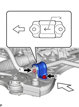
| *a | Arrow |
|
|
Front of the Vehicle |
Install the front No. 1 stabilizer bracket LH to the front frame assembly with the 2 bolts.
- Torque:
- 44 N*m (449 kgf*cm, 32 ft.*lbf)
- NOTICE:
- ·
Make sure to install the front No. 1 stabilizer bracket LH with its arrow facing the front of the vehicle.
·Temporarily tighten the bolt (B) and then fully tighten the 2 bolts in the order of (A) and (B).
48824A
5.INSTALL FRONT NO. 1 STABILIZER BRACKET RH
- HINT:
-
Perform the same procedure as for the LH side.
48826F
6.INSTALL STABILIZER PROTECTOR (for Gasoline Model)
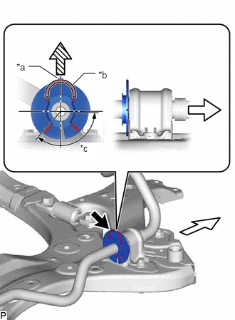
| *a | Protrusion |
| *b | Curled Top of Clip |
| *c | Notch Area |
|
|
Right Side of Vehicle |

|
Upper Side of Vehicle |
Install the stabilizer protector to the front stabilizer bar.
- NOTICE:
- ·
Install the stabilizer protector so that the protrusion is facing the upper side of the vehicle.
·Press the stabilizer protector so that it contacts the side of the front No. 1 stabilizer bar bushing and install the stabilizer protector.
Install the clip.
- NOTICE:
-
Install so that the curled top of the clip does not enter the notch area.
7.INSTALL ENGINE ASSEMBLY WITH TRANSAXLE
for A25F-FXS [Production Date from 2021/08]:
48810
8.INSTALL FRONT STABILIZER LINK ASSEMBLY LH
Install the front stabilizer link assembly LH to the front stabilizer bar with the nut.
- Torque:
- 74 N*m (755 kgf*cm, 55 ft.*lbf)
- NOTICE:
-
Do not damage the boot of the ball joint.
- HINT:
-
If the ball joint turns together with the nut, use a 6 mm hexagon socket wrench to hold the stud bolt.
48820B
9.INSTALL FRONT STABILIZER LINK ASSEMBLY RH
- HINT:
-
Perform the same procedure as for the LH side.