SEAT REAR SEAT ASSEMBLY(for SFTM Made) INSTALLATION
CAUTION / NOTICE / HINT
- CAUTION:
- ·
Wear protective gloves. Sharp areas on the parts may injure your hands.
·There is risk of injury.
PROCEDURE

 72602A
1.INSTALL REAR SEAT BACK LOCK STRIKER SUB-ASSEMBLY LH
72602A
1.INSTALL REAR SEAT BACK LOCK STRIKER SUB-ASSEMBLY LH
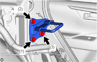
Temporarily install the rear seatback lock striker sub-asembly LH with the bolt A.
Tighten the 3 bolts in the order shown in the illustration.
- Torque:
- 18.1 N*m (185 kgf*cm, 13 ft.*lbf)
72601A
2.INSTALL REAR SEAT BACK LOOK STRIKER SUB-ASSEMBLY RH
- HINT:
-
Use the same procedure described for the LH side.
64740E
3.INSTALL DECK TRIM SIDE PANEL ASSEMBLY LH
64730J
4.INSTALL DECK TRIM SIDE PANEL ASSEMBLY RH
65351A
5.INSTALL BATTERY HOLE COVER (for HV Model)
58460D
6.INSTALL LUGGAGE HOLD BELT STRIKER ASSEMBLY
73708A
7.INSTALL TETHER ANCHOR BRACKET SET
62552F
8.INSTALL REAR SEAT SIDE GARNISH LH
62551F
9.INSTALL REAR SEAT SIDE GARNISH RH
- HINT:
-
Use the same procedure described for the LH side.
62332C
10.INSTALL REAR DOOR OPENING TRIM WEATHERSTRIP LH
62331C
11.INSTALL REAR DOOR OPENING TRIM WEATHERSTRIP RH
- HINT:
-
Use the same procedure described for the LH side.
58577E
12.INSTALL REAR NO. 1 FLOOR MAT SUPPORT SIDE PLATE
71033
13.INSTALL REAR SEAT CUSHION LEG SUB-ASSEMBLY (for HV Model)
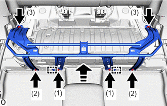

|
Install in this Direction |
Attach the guide.
Temporarily install the rear seat cushion leg sub-assembly with the 6 bolts.
Tighten the 6 bolts in the order shown in the illustration.
- Torque:
- 19.5 N*m (199 kgf*cm, 14 ft.*lbf)
58464D
14.INSTALL BATTERY SERVICE COVER BOARD (for HV Model)
58467H
15.INSTALL NO. 3 BATTERY SERVICE COVER BOARD (for HV Model)
58466J
16.INSTALL NO. 2 BATTERY SERVICE COVER BOARD (for HV Model)
67918E
17.INSTALL REAR DOOR SCUFF PLATE LH
67917C
18.INSTALL REAR DOOR SCUFF PLATE RH
- HINT:
-
Use the same procedure as for the LH side.
71304C
19.INSTALL REAR SEATBACK HINGE SUB-ASSEMBLY LH
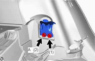
Temporarily install the rear seatback hinge sub-assembly LH with the bolt A.
Tighten the 2 bolts in the order shown in the illustration.
- Torque:
- 36.8 N*m (375 kgf*cm, 27 ft.*lbf)
71303C
20.INSTALL REAR SEATBACK HINGE SUB-ASSEMBLY RH
- HINT:
-
Use the same procedure as for the LH side.
71305A
21.INSTALL REAR CENTER SEATBACK HINGE SUB-ASSEMBLY
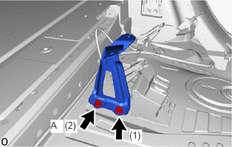
Temporarily install the rear center seatback hinge sub-assembly with the bolt A.
Tighten the 2 bolts in the order shown in the illustration.
- Torque:
- 36.8 N*m (375 kgf*cm, 27 ft.*lbf)
22.INSTALL REAR SEATBACK ASSEMBLY RH
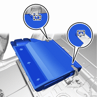
Attach the guide.
- NOTICE:
-
Be careful not to damage the rear seatback assembly RH, body exterior or interior parts.
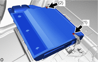
Install the rear seatback assembly RH with the 2 bolts in the order shown in the illustration.
- Torque:
- 36.8 N*m (375 kgf*cm, 27 ft.*lbf)
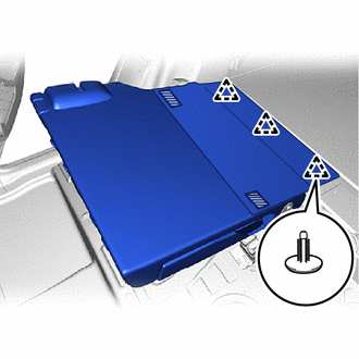

|
Fastening tape |
Attach the fastening tape.
Install 3 new clips.
- NOTICE:
-
Check that the claw of the clip is securely attached.
Attach the clip.
Return the rear seatback assembly RH.
73350C
23.INSTALL REAR CENTER SEAT OUTER BELT ASSEMBLY (FLOOR ANCHOR)
24.INSTALL REAR SEATBACK ASSEMBLY LH
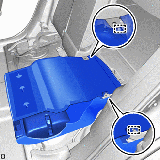
Attach the guide.
- NOTICE:
-
Be careful not to damage the rear seatback assembly LH, body exterior or interior parts.
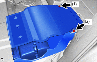
Install the rear seatback assembly LH with the 2 bolts in the order shown in the illustration.
- Torque:
- 36.8 N*m (375 kgf*cm, 27 ft.*lbf)
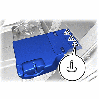
|
|
Fastening tape |
Attach the fastening tape.
Install 3 new clips.
- NOTICE:
-
Check that the claw of the clip is securely attached.
Attach the clip.
Return the rear seatback assembly LH.
72693
25.INSTALL REAR SEAT CUSHION LOCK HOOK
- HINT:
-
Use the same procedure for the 2 parts.
Set a new rear seat cushion lock hook.
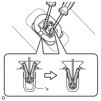
| *a | Sleeve |
|
|
Protective Tape |
Using 2 thin-bladed screwdrivers, push the sleeve to attach the claw.
- NOTICE:
-
Do not apply excessive force which may break the sleeve.
- HINT:
-
Tape the thin-bladed screwdriver tip before use.
Check the installation condition.
- OK:
The sleeve is installed properly.
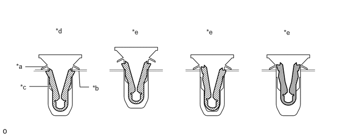
| *a | Body | *b | Vehicle |
| *c | Sleeve | *d | Correct |
| *e | Incorrect | - | - |
26.INSTALL BENCH TYPE REAR SEAT CUSHION ASSEMBLY
Place the bench type rear seat cushion assembly in the vehicle.
- NOTICE:
-
Be careful not to damage the bench type rear seat cushion assembly, body exterior or interior parts.
for Gasoline Model
Attach the cushion wire on the 2 child restraint seat anchor bracket sub-assemblies as shown in the illustration.
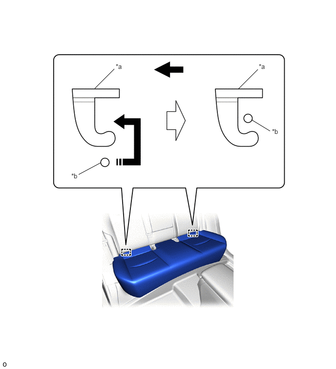
| *a | Child Restraint Seat Anchor Bracket Sub-assembly | *b | Cushion Wire |
|
|
Install in this Direction | 
|
Front Side |
for HV Model
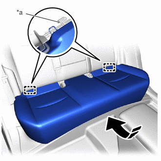
| *a | Child Restraint Seat Anchor Bracket Sub-assembly |
|
|
Install in this Direction |
Attach the cushion wire on the rear end of bench type rear seat cushion assembly under the 2 child restraint seat anchor bracket sub-assemblies.
Push in the installation direction shown in the illustration and attach the hook on the front of bench type rear seat cushion assembly to the rear seat cushion lock hook.
- NOTICE:
- ·
Be sure to attach the hook on the front of bench type rear seat cushion assembly one at a time.
·Check that the rear seat cushion lock hook and bench type rear seat cushion assembly are securely fastened.
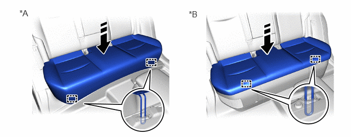
| *A | for Gasoline Model | *B | for HV Model |
|
|
Install in this Direction | - | - |
71960B
27.INSTALL REAR CENTER SEAT HEADREST ASSEMBLY
Install the rear center seat headrest assembly.
71940A
28.INSTALL REAR SEAT HEADREST ASSEMBLY
Install the 2 rear seat headrest assemblies.
58386
29.INSTALL REAR FLOOR FINISH PLATE
58417H
30.INSTALL REAR NO. 3 FLOOR BOARD
58416K
31.INSTALL REAR NO. 2 FLOOR BOARD
58410B
32.INSTALL DECK BOARD ASSEMBLY