☰ Toyota RAV4☰ فهرستVehicle Interior › MIRROR (INT) › DIGITAL REAR-VIEW MIRROR SYSTEM(for Gasoline Model)
RM36D0EC
_58
Vehicle Interior
_083098
MIRROR (INT)
_0417435
DIGITAL REAR-VIEW MIRROR SYSTEM(for Gasoline Model)
J
MIRROR (INT) DIGITAL REAR-VIEW MIRROR SYSTEM(for Gasoline Model) The Camera Indicator is not Displayed
DESCRIPTION
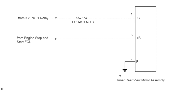
Power is supplied to the inner rear view mirror assembly through this circuit.
WIRING DIAGRAM
0.698,1.5 2.083,1.833
1.385,0.333
10
false
from Engine Stop and Start ECU
0.75,0.667 2.063,0.896
1.313,0.229
10
false
from IG1 NO.1 Relay
3,0.844 3.969,1.083
0.969,0.24
10
false
ECU-IG1 NO.3
4.896,3.104 5.208,3.302
0.313,0.198
10
false
P1
4.885,3.271 6.938,3.49
2.052,0.219
10
false
Inner Rear View Mirror Assembly
5.688,1.5 6,1.698
0.313,0.198
10
false
+B
5.688,0.667 6,0.865
0.313,0.198
10
false
IG
5.677,2.5 5.833,2.698
0.156,0.198
10
false
E
5.448,1.385 5.604,1.583
0.156,0.198
10
false
6
5.448,0.51 5.604,0.708
0.156,0.198
10
false
1
5.438,2.385 5.594,2.583
0.156,0.198
10
false
2
CAUTION / NOTICE / HINT
- NOTICE:
-
Inspect the fuses for circuits related to this system before performing the following procedure.
PROCEDURE
1.CHECK HARNESS AND CONNECTOR (INNER REAR VIEW MIRROR ASSEMBLY - BATTERY)
a.
1.51,0.25 1.917,0.51
0.406,0.26
0.75,1.885 0.958,1.885
0.958,1.885 1.313,1.531
true
0.063,0.031 0.375,0.188
0.313,0.156
10
false
*a
1.625,0.292 2.083,0.49
0.458,0.198
10
false
P1
0.5,1.802 0.813,2
0.313,0.198
10
false
+B
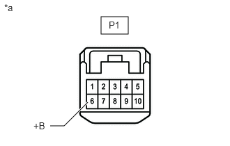
| *a | Front view of wire harness connector
(to Inner Rear View Mirror Assembly) |
Disconnect the inner rear view mirror assembly connector.
b.
Measure the voltage according to the value(s) in the table below.
- Standard Voltage:
Tester Connection Condition Specified Condition P1-6 (+B) - Body ground Always 9.5 to 14 V
- Result:
Proceed to OK NG
OK
2.CHECK HARNESS AND CONNECTOR (INNER REAR VIEW MIRROR ASSEMBLY - BATTERY)
NG
2.CHECK HARNESS AND CONNECTOR (INNER REAR VIEW MIRROR ASSEMBLY - BATTERY)
a.
1.51,0.25 1.917,0.51
0.406,0.26
0.75,0.875 0.958,0.875
0.958,0.875 1.313,1.25
true
0.063,0.031 0.375,0.188
0.313,0.156
10
false
*a
1.625,0.292 2.083,0.49
0.458,0.198
10
false
P1
0.542,0.792 0.854,0.99
0.313,0.198
10
false
IG
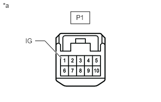
| *a | Front view of wire harness connector
(to Inner Rear View Mirror Assembly) |
Disconnect the inner rear view mirror assembly connector.
b.
Measure the voltage according to the value(s) in the table below.
- Standard Voltage:
Tester Connection Switch Condition Specified Condition P1-1 (IG) - Body ground Engine switch on (IG) 11 to 14 V
- Result:
Proceed to OK NG
OK
3.CHECK HARNESS AND CONNECTOR (INNER REAR VIEW MIRROR ASSEMBLY - BODY GROUND)
NG
REPAIR OR REPLACE HARNESS OR CONNECTOR
3.CHECK HARNESS AND CONNECTOR (INNER REAR VIEW MIRROR ASSEMBLY - BODY GROUND)
a.
1.51,0.25 1.917,0.51
0.406,0.26
0.802,0.75 1.01,0.75
1.01,0.75 1.5,1.25
true
0.063,0.031 0.375,0.188
0.313,0.156
10
false
*a
1.625,0.292 2.083,0.49
0.458,0.198
10
false
P1
0.594,0.667 0.906,0.865
0.313,0.198
10
false
E
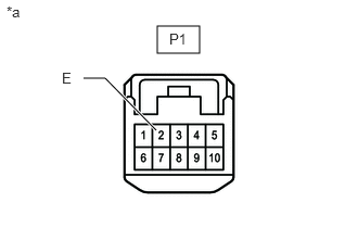
| *a | Front view of wire harness connector
(to Inner Rear View Mirror Assembly) |
Disconnect the inner rear view mirror assembly connector.
b.
Measure the resistance according to the value(s) in the table below.
- Standard Resistance:
Tester Connection Condition Specified Condition P1-2 (E) - Body ground Always Below 1 Ω
- Result:
Proceed to OK NG
OK
REPLACE INNER REAR VIEW MIRROR ASSEMBLY
NG
REPAIR OR REPLACE HARNESS OR CONNECTOR