DOOR / HATCH REAR DOOR ADJUSTMENT
CAUTION / NOTICE / HINT
- HINT:
- ·
Use the same procedure for the RH and LH sides.
·The procedure listed below is for the LH side.
·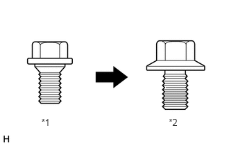 0.621,1.754 0.818,1.944 0.197,0.19 10 *1 2.535,1.754 2.732,1.944 0.197,0.19 10 *2
*1 Centering Bolt *2 Standard Bolt
Centering bolts are used to mount the door hinge to the vehicle body and door. The door cannot be adjusted with the centering bolts on. Substitute the centering bolts for standard bolts when making adjustments.
·A bolt without a torque specification is shown in the standard bolt chart.
PROCEDURE

 67004
1.INSPECT REAR DOOR PANEL SUB-ASSEMBLY LH
67004
1.INSPECT REAR DOOR PANEL SUB-ASSEMBLY LH
Check that the clearance measurements of areas A to K are within the standard ranges.
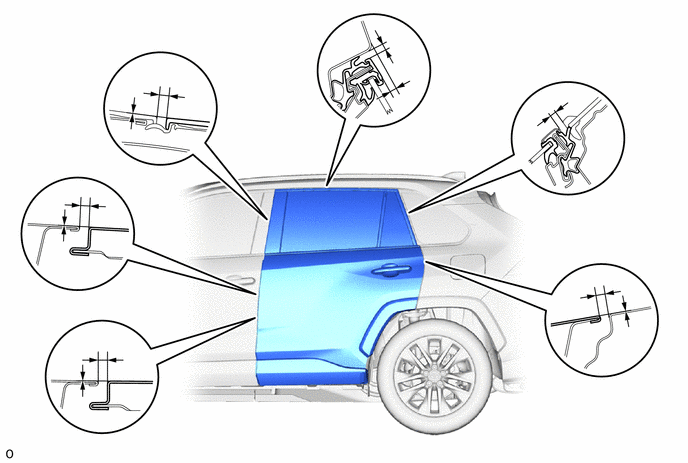
| Area | Measurement | Area | Measurement |
|---|---|---|---|
| A
(Reference) |
5.1 mm (0.201 in.) | B
(Reference) |
0 mm (0 in.) |
| C | 2.9 to 5.3 mm (0.114 to 0.209 in.) | D | -1.5 to 0.9 mm (-0.0591 to 0.0354 in.) |
| E | 2.9 to 5.3 mm (0.114 to 0.209 in.) | F | -1.5 to 0.9 mm (-0.0591 to 0.0354 in.) |
| G | 2.65 to 6.05 mm (0.104 to 0.238 in.) | H | 3.15 to 7.15 mm (0.124 to 0.281 in.) |
| I | 3.3 to 7.3 mm (0.130 to 0.287 in.) | J | 2.2 to 5.2 mm (0.0866 to 0.2047 in.) |
| K | -1.8 to 1.2 mm (-0.0709 to 0.0472 in.) | - | - |
67004
2.ADJUST REAR DOOR PANEL SUB-ASSEMBLY LH
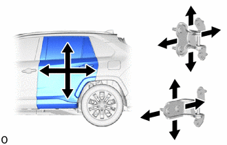
Loosen the hinge bolts on the body and adjust the door position.
Tighten the hinge bolts on the body after the adjustment.
- Torque:
- 26 N*m (265 kgf*cm, 19 ft.*lbf)
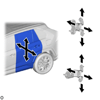
Loosen the hinge bolts on the door and adjust the door position.
Tighten the hinge bolts on the door after the adjustment.
- Torque:
- 21 N*m (214 kgf*cm, 15 ft.*lbf)
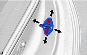
Using a T40 "TORX" socket wrench, adjust the striker position by slightly loosening the striker mounting screws and hitting the striker with a brass bar and a hammer.
Using a T40 "TORX" socket wrench, tighten the striker mounting screws after the adjustment.
- Torque:
- 23 N*m (235 kgf*cm, 17 ft.*lbf)