M20D-FKS COOLING FLOW SHUTTING VALVE(for Heater) INSTALLATION
PROCEDURE

 16260
1.INSTALL FLOW SHUTTING VALVE (WATER BY-PASS HOSE ASSEMBLY)
16260
1.INSTALL FLOW SHUTTING VALVE (WATER BY-PASS HOSE ASSEMBLY)
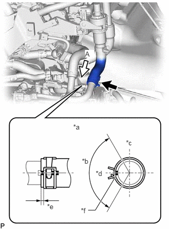
| *a | View A |
| *b | 120° |
| *c | Upper Side |
| *d | Rear Side |
| *e | 2 to 7 mm (0.0787 to 0.276 in.) |
| *f | Paint Mark |
Connect the flow shutting valve (water by-pass hose assembly) to the water by-pass outlet sub-assembly and slide the clip to secure it.
- NOTICE:
- ·
Make sure to slide the flow shutting valve (water by-pass hose assembly) until it contacts the hose stopper of the water by-pass outlet sub-assembly.
·Make sure that the tabs of the clip are within the area shown in the illustration.
Connect the flow shutting valve (water by-pass hose assembly) with the bolt.
- Torque:
- 19 N*m (194 kgf*cm, 14 ft.*lbf)
Connect the No. 2 water by-pass pipe sub-assembly with the bolt.
- Torque:
- 19 N*m (194 kgf*cm, 14 ft.*lbf)
Connect the outlet heater water hose connector to the No. 2 water by-pass pipe sub-assembly.
- NOTICE:
-
Check that there is no damage or foreign matter on the connecting parts of the water lines.
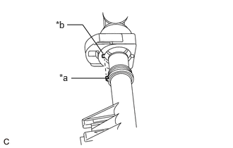
| *a | Protrusion |
| *b | Cutout |
Align the protrusion of the No. 2 water by-pass pipe sub-assembly with the cutout in the outlet heater water hose connector and securely insert the outlet heater water hose connector to the stopper of the pipe.
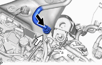
| *a | Retainer |

|
Push |

|
Push in |
Push in the retainer.
Check that the No. 2 water by-pass pipe sub-assembly and outlet heater water hose connector are securely connected by pulling on them.
Connect the inlet heater water hose connector to the flow shutting valve (water by-pass hose assembly).
- NOTICE:
-
Check that there is no damage or foreign matter on the connecting parts of the water lines.
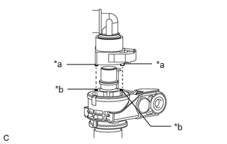
| *a | Protrusion |
| *b | Cutout |
Align the protrusions of the inlet heater water hose connector with the cutouts in the flow shutting valve (water by-pass hose assembly) and securely insert the inlet heater water hose connector to the stopper of the pipe.
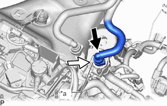
| *a | Retainer |
|
|
Push |
|
|
Push in |
Push in the retainer.
Check that the flow shutting valve (water by-pass hose assembly) and inlet heater water hose connector are securely connected by pulling on them.
Connect the flow shutting valve (water by-pass hose assembly) connector.
2.INSTALL BATTERY
3.ADD ENGINE COOLANT
4.INSPECT FOR COOLANT LEAK
51420
5.INSTALL NO. 2 ENGINE UNDER COVER ASSEMBLY
51441
6.INSTALL NO. 1 ENGINE UNDER COVER
53896B
7.INSTALL FRONT FENDER FRONT SPLASH SHIELD LH
53895B
8.INSTALL FRONT FENDER FRONT SPLASH SHIELD RH