RM36D0EC
_52
Drivetrain
_083070
DRIVE SHAFT / PROPELLER SHAFT
_0403352
PROPELLER SHAFT ASSEMBLY
G
DRIVE SHAFT / PROPELLER SHAFT PROPELLER SHAFT ASSEMBLY INSPECTION
PROCEDURE

 1.INSPECT PROPELLER SHAFT ASSEMBLY
a.
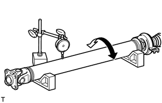
Using a dial indicator, measure the propeller shaft runout for the front side.
- Maximum runout:
0.4 mm (0.0157 in.)
If the shaft runout is more than the maximum, replace the propeller shaft.
- NOTICE:
-
Place the dial indicator on the center of the shaft, and perpendicular to the shaft.
b.
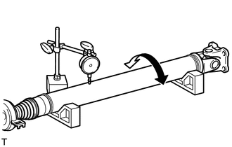
Using a dial indicator, measure the propeller shaft runout for the rear side.
- Maximum runout:
0.4 mm (0.0157 in.)
If the shaft runout is more than the maximum, replace the propeller shaft.
- NOTICE:
-
Place the dial indicator on the center of the shaft, and perpendicular to the shaft.