RM36D0EC
_52
Drivetrain
_083070
DRIVE SHAFT / PROPELLER SHAFT
_0403350
REAR DRIVE SHAFT ASSEMBLY
G
DRIVE SHAFT / PROPELLER SHAFT REAR DRIVE SHAFT ASSEMBLY INSPECTION
CAUTION / NOTICE / HINT
- NOTICE:
- ·
When using a vise, place aluminum plates between the part and vise.
·When using a vise, do not overtighten it.
PROCEDURE

 1.INSPECT REAR DRIVE SHAFT ASSEMBLY
a.
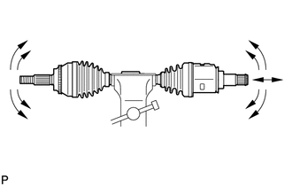
Check that there is no excessive play in the radial direction of the outboard joint.
b.
Check that the inboard joint slides smoothly in the thrust direction.
c.
Check that there is no excessive play in the radial direction of the inboard joint.
d.
Check the boots for damage.
e.
1.438,1.521 1.656,1.74
0.219,0.219
10
(A)
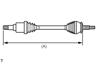
Check whether the drive shaft dimension (A) is within specification.
i.
for Gasoline Model
- Length (A):
Item Length for Torque Vectoring Differential LH Side 626.4 mm (2.05 ft.) RH Side 611.4 mm (2.01 ft.) except Torque Vectoring Differential 755.3 mm (2.48 ft.)
ii.
for HV Model
- Length (A):
Item Length for Type A
(SFTC made)LH Side 718.4 mm (2.36 ft.) RH Side 791.4 mm (2.60 ft.) for Type B
(GTMC made)LH Side 754.35 mm (2.47 ft.) RH Side 790.45 mm (2.59 ft.)
- NOTICE:
-
Keep the drive shaft assembly level during inspection.
If the boots are stretched or contracted, correct them.