☰ Toyota RAV4☰ فهرستAudio / Visual / Telematics › PARK ASSIST / MONITORING › PANORAMIC VIEW MONITOR SWITCH
RM36D0EC
_56
Audio / Visual / Telematics
_083082
PARK ASSIST / MONITORING
_0403110
PANORAMIC VIEW MONITOR SWITCH
G
PARK ASSIST / MONITORING PANORAMIC VIEW MONITOR SWITCH INSPECTION
PROCEDURE

 84721B
1.INSPECT PANORAMIC VIEW MONITOR SWITCH
84721B
1.INSPECT PANORAMIC VIEW MONITOR SWITCH
a.
1.448,2.917 1.448,2.583
true
1.938,2.917 1.938,2.583
true
0.083,0.083 0.396,0.281
0.313,0.198
10
false
*a
1.417,2.938 1.573,3.135
0.156,0.198
10
false
D
1.917,2.927 2.073,3.125
0.156,0.198
10
false
E
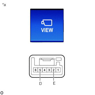
| *a | Component without harness connected
(Panoramic View Monitor Switch) |
Measure the resistance according to the value(s) in the table below.
- Standard Resistance:
Tester Connection Switch Condition Specified Condition If the result is not as specified, replace the panoramic view monitor switch.
5 (D) - 2 (E) Panoramic view monitor switch on (not protruding) Below 1 Ω Panoramic view monitor switch off (protruding) 10 kΩ or higher
b.
1.281,2.917 1.281,2.583
true
2.104,2.917 2.104,2.583
true
1.198,2.927 1.531,3.094
0.333,0.167
10
false
ILL+
2.031,2.927 2.365,3.094
0.333,0.167
10
false
ILL-
0.083,0.083 0.396,0.281
0.313,0.198
10
false
*a
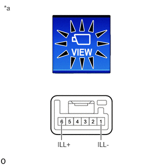
| *a | Component without harness connected
(Panoramic View Monitor Switch) |
Check that the switch illuminates.
i.
Apply auxiliary battery voltage to the panoramic view monitor switch and check that the switch illuminates.
- OK:
Auxiliary Battery Connection Specified Condition If the result is not as specified, replace the panoramic view monitor switch.
Auxiliary Battery positive (+) → Terminal 6 (ILL+)
Auxiliary Battery negative (-) → Terminal 1 (ILL-)Illuminates