M20D-FKS ENGINE MECHANICAL CYLINDER HEAD REASSEMBLY
PROCEDURE

 1.INSTALL SPARK PLUG TUBE
- HINT:
-
When using a new cylinder head sub-assembly, the spark plug tubes must be replaced.
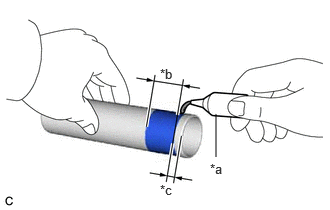
| *a | Adhesive |
| *b | Application Width |
| *c | Distance |
Apply adhesive to a new spark plug tube as shown in the illustration.
- Adhesive:
Toyota Genuine Adhesive 1324, Three Bond 1324 or equivalent
- Standard Application Width:
1.0 to 7.0 mm (0.0394 to 0.276 in.)
- Distance:
1.0 mm (0.0394 in.)
- NOTICE:
- ·
Install the spark plug tube within 3 minutes of applying adhesive.
·Be careful not to deform the spark plug tube.
·Do not expose the spark plug tube to engine oil for at least 1 hour after installing it.
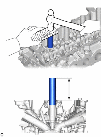
| *a | Protrusion Height |
Using a wooden block and hammer, tap in the 4 spark plug tubes to the specified protrusion height.
- Standard Protrusion Height:
77.3 to 78.3 mm (3.04 to 3.08 in.)
- NOTICE:
-
To avoid tapping in the spark plug tube too far, measure the protrusion height while tapping it.
17159
2.INSTALL STUD BOLT
- NOTICE:
-
If a stud bolt is deformed or its threads are damaged, replace it.
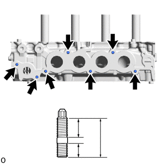
| *a | 20 mm (0.787 in.) |
| *b | 35 mm (1.38 in.) |
| *c | 13 mm (0.512 in.) |
Using an E8 "TORX" socket wrench, install the 7 stud bolts.
- Torque:
- 6.5 N*m (66 kgf*cm, 58 in.*lbf)
11117E
3.INSTALL NO. 1 STRAIGHT SCREW PLUG
- HINT:
-
If coolant leaks from a No. 1 straight screw plug or a plug is corroded, replace it.
Apply adhesive to the 4 No. 1 straight screw plugs.
- Adhesive:
Toyota Genuine Adhesive 1324, Three Bond 1324 or equivalent
- NOTICE:
-
Install the No. 1 straight screw plugs within 3 minutes of applying adhesive.
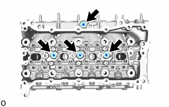
Using a 6 mm straight hexagon wrench, install the 4 No. 1 straight screw plugs to the cylinder head sub-assembly.
- Torque:
- 25 N*m (255 kgf*cm, 18 ft.*lbf)
4.INSTALL VALVE SPRING SEAT
Install the 16 valve spring seats to the cylinder head sub-assembly.
5.INSTALL VALVE STEM OIL SEAL
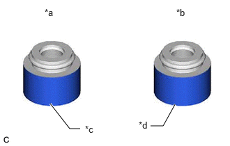
| *a | Intake Valve Stem Oil Seal |
| *b | Exhaust Valve Stem Oil Seal |
| *c | Gold |
| *d | Gray |
Apply a light coat of engine oil to 16 new valve stem oil seals.
- NOTICE:
-
Make sure to install each valve stem oil seal to the correct side. Installing an intake valve stem oil seal to the exhaust side or installing an exhaust valve stem oil seal to the intake side can cause installation problems later.
- HINT:
-
The intake valve stem oil seals are gold and the exhaust valve stem oil seals are gray.

| *a | Correct |
| *b | Incorrect |
Using SST, push in the 16 valve stem oil seals.
- SST
- 09201-41020
- NOTICE:
- ·
Failure to use SST will cause the valve stem oil seals to be damaged or improperly seated.
·Do not push in the valve stem oil seals at an angle.
13711
6.INSTALL INTAKE VALVE
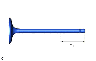
| *a | 30 mm (1.18 in.) or more |
Sufficiently apply engine oil to the tip area of the intake valve shown in the illustration.
Install the 8 intake valves, 8 compression springs and 8 valve spring retainers to the cylinder head sub-assembly.
- NOTICE:
-
Install the same parts in the same combination to their original locations.

Using SST, compress each compression spring and install the 8 valve spring retainer locks.
- SST
- 09202-70020 (09202-01010, 09202-01020)
09202-00021
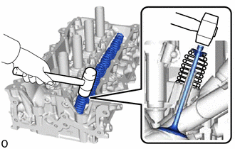
Using a plastic-faced hammer, lightly tap the valve stem tip to ensure a proper fit.
- NOTICE:
- ·
Be careful not to damage the valve stem tip.
·Be careful not to damage the valve spring retainer.
13715
7.INSTALL EXHAUST VALVE
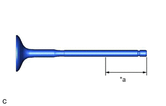
| *a | 30 mm (1.18 in.) or more |
Sufficiently apply engine oil to the tip area of the exhaust valve shown in the illustration.
Install the 8 exhaust valves, 8 compression springs and 8 valve spring retainers to the cylinder head sub-assembly.
- NOTICE:
-
Install the same parts in the same combination to their original locations.
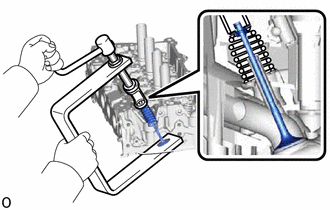
Using SST, compress each compression spring and install the 8 valve spring retainer locks.
- SST
- 09202-70020 (09202-01010, 09202-01020)
09202-00021
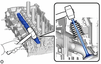
Using a plastic-faced hammer, lightly tap the valve stem tip to ensure a proper fit.
- NOTICE:
- ·
Be careful not to damage the valve stem tip.
·Be careful not to damage the valve spring retainer.