AXLE AND DIFFERENTIAL REAR DIFFERENTIAL CARRIER ASSEMBLY(for Torque Vectoring Differential) REASSEMBLY
PROCEDURE

 41201C
1.INSTALL REAR DIFFERENTIAL CARRIER OIL SEAL (for LH Side)
41201C
1.INSTALL REAR DIFFERENTIAL CARRIER OIL SEAL (for LH Side)
41201C
2.INSTALL REAR DIFFERENTIAL CARRIER OIL SEAL (for RH Side)
41110K
3.INSTALL REAR DIFFERENTIAL BREATHER PLUG
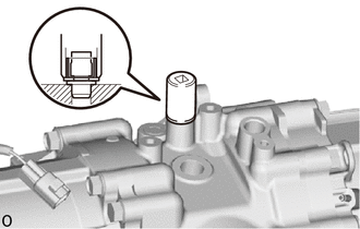
| *1 | Rear Differential Carrier Cover Breather Plug |
| *a | Service Nut |
| *b | Socket Wrench |
Using a socket wrench, service nut and hammer, install a new rear differential breather plug to the rear differential carrier.
- HINT:
- ·
Use a service nut with an inner diameter of 13 mm (0.512 in.) and a socket wrench appropriate for the service nut.
·Tap in the rear differential breather plug until it sits flush with the rear differential carrier assembly.
89429F
4.INSTALL TEMPERATURE SENSOR
84546A
5.INSTALL NO. 2 4 WHEEL DRIVE POSITION SWITCH
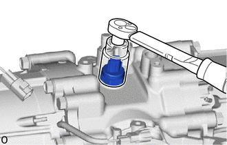
Using SST, install the No. 2 4 wheel drive position switch to the rear differential carrier assembly.
- SST
- 09816-30010
- Torque:
- 40.2 N*m (410 kgf*cm, 30 ft.*lbf)
89413A
6.INSTALL TRANSMISSION REVOLUTION SENSOR
Apply gear oil to a new O-ring.
Install the O-ring to the transmission revolution sensor.
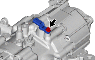
Install the transmission revolution sensor to the rear differential carrier assembly with the bolt.
- Torque:
- 6.5 N*m (66 kgf*cm, 58 in.*lbf)
41108A
7.INSTALL REAR DIFFERENTIAL CARRIER COVER PLUG
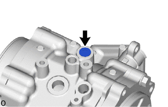
Using an 8 mm socket hexagon wrench, install a new rear differential carrier cover plug to the rear differential carrier sub-assembly.
- Torque:
- 30 N*m (306 kgf*cm, 22 ft.*lbf)
41110H
8.INSTALL REAR DIFFERENTIAL FILLER PLUG
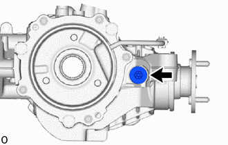
Using a 10 mm socket hexagon wrench, install a new gasket and the rear differential filler plug.
- Torque:
- 39 N*m (398 kgf*cm, 29 ft.*lbf)
41110D
9.INSTALL REAR DIFFERENTIAL DRAIN PLUG
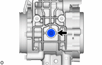
Using a 10 mm socket hexagon wrench, install a new gasket and the rear differential drain plug.
- Torque:
- 39 N*m (398 kgf*cm, 29 ft.*lbf)
41330M
10.INSTALL TRANSMISSION COUPLING DUST SEAL (for LH Side)
| *1 | Transmission Coupling Dust Seal |
| *a | Cloth |
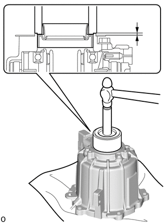
Using SST and a hammer, install a new transmission coupling dust seal into the electro magnetic control coupling sub-assembly.
- SST
- 09316-10010
09950-70010 (09951-07150)
- Standard Distance (A):
2.0 to 2.8 mm (0.0788 to 0.1102 in.)
- NOTICE:
- ·
Install the transmission coupling dust seal uniformly.
·Press fit the transmission coupling dust seal straight.
·Do not damage the transmission coupling dust seal.
·Do not excessively press in the transmission coupling dust seal.
·Make sure to install the transmission coupling dust seal as specified, otherwise a malfunction such as an oil leak may occur.
- HINT:
-
Make sure to place the electro magnetic control coupling sub-assembly on a clean piece of cloth when performing this step.
Apply a light coat of MP grease to the lip of the rear drive shaft oil seal.
41330M
11.INSTALL TRANSMISSION COUPLING DUST SEAL (for RH Side)
- HINT:
-
Perform the same procedure as for the LH side.
12.INSTALL ELECTRO MAGNETIC CONTROL COUPLING SUB-ASSEMBLY (for LH Side)
Apply gear oil to a new O-ring.
Install the O-ring to the differential side bearing retainer.
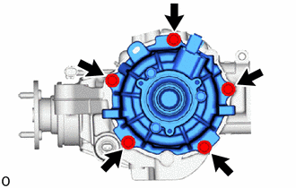
Install the electro magnetic control coupling sub-assembly to the differential bearing retainer with the 5 bolts.
- Torque:
- 47 N*m (479 kgf*cm, 35 ft.*lbf)
13.INSTALL ELECTRO MAGNETIC CONTROL COUPLING SUB-ASSEMBLY (for RH Side)
- HINT:
-
Perform the same procedure as for the LH side.
41252
14.INSTALL NO. 1 REAR DIFFERENTIAL DUST DEFLECTOR (for LH Side)
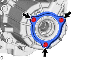
| *1 | No. 1 Rear Differential Dust Deflector |
| *2 | No. 2 Rear Differential Dust Deflector |
Install the No. 1 rear differential dust deflector and No. 2 rear differential dust deflector to the electro magnetic control coupling sub-assembly with the 3 bolts.
- Torque:
- 5.4 N*m (55 kgf*cm, 48 in.*lbf)
41252
15.INSTALL NO. 1 REAR DIFFERENTIAL DUST DEFLECTOR (for RH Side)
- HINT:
-
Perform the same procedure as for the LH side.
41201C
16.INSTALL REAR DIFFERENTIAL CARRIER OIL SEAL (for Front Side)
41204
17.INSTALL REAR DRIVE PINION COMPANION FLANGE SUB-ASSEMBLY
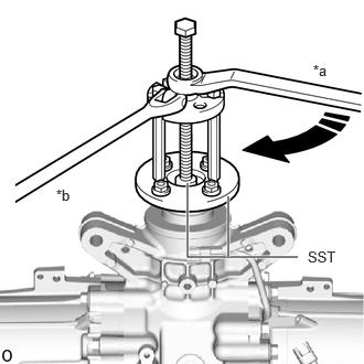
| *a | Turn |
| *b | Hold |
Using SST, install the rear drive pinion companion flange sub-assembly.
- SST
- 09950-30012 (09951-03010, 09953-03010, 09954-03010, 09955-03030, 09956-03020)
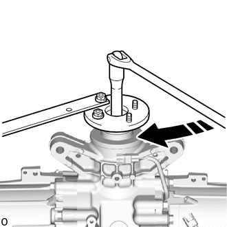
| *a | Turn |
| *b | Hold |
Using SST, temporarily install the rear drive pinion nut.
- SST
- 09330-00021
- Torque:
- 140 N*m (1428 kgf*cm, 103 ft.*lbf)
- CAUTION:
-
The total preload may be within the standard even when the output shaft companion flange is loose. If the output shaft companion flange is installed in this state, the vehicle may be damaged or lead to a serious accident.
- NOTICE:
-
Tighten the output shaft companion flange nut until there is no more looseness in the rear drive pinion companion flange sub-assembly and it turns to the right and left with the same amount of force.
- HINT:
-
After temporarily installing the output shaft companion flange nut, be sure to adjust the preoload.
18.INSPECT TOTAL PRELOAD
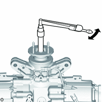
Using a torque wrench, measure the total preload (starting torque) with the teeth of the differential drive pinion and differential ring gear in contact.
- HINT:
- ·
The torque wrench should be installed as shown in the illustration.
·For a more accurate measurement, rotate the bearing forward and backward several times before the measurement.
·Use the preload value measured prior to disassembling the torque vectoring differential carrier assembly as the standard value.
·Adjust within the standard value (Adjustable range within +/- 0.2 N*m of the measured preload value).
If the preload is not as specified, perform the procedures below.
If the measured preoload is higher than the standard value:
Replace the rear drive pinion bearing and differential pinion bearing spacer, and then adjust the preload again.
If the measured preoload is lower than the standard value:
Tighten the rear drive pinion companion flange nut, and then adjust the preload again.
41204B
19.INSTALL REAR DRIVE PINION NUT
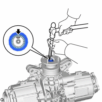
Using chisel and a hammer, stake the rear drive pinion nut.
41173A
20.INSTALL NO. 2 DIFFERENTIAL DISCONNECT COVER
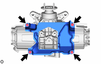
Install the No. 2 differential disconnect cover to the torque vectoring differential carrier assembly with the 4 bolts.
- Torque:
- 19.6 N*m (200 kgf*cm, 14 ft.*lbf)
41173
21.INSTALL DIFFERENTIAL DISCONNECT COVER
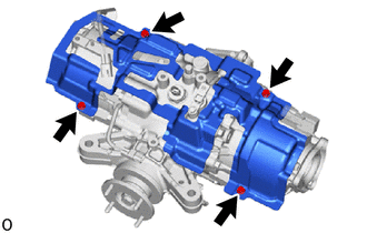
Install the differential disconnect cover to the torque vectoring differential carrier assembly with the 4 bolts.
- Torque:
- 6.5 N*m (66 kgf*cm, 58 in.*lbf)
22.INSTALL WIRE HARNESS CLAMP BRACKET
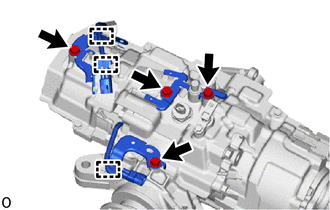
Install the 4 wire harness clamp brackets to the torque vectoring differential carrier assembly with the 4 bolts.
- Torque:
- 19.6 N*m (200 kgf*cm, 14 ft.*lbf)
Engage the 3 clamps.
31364D
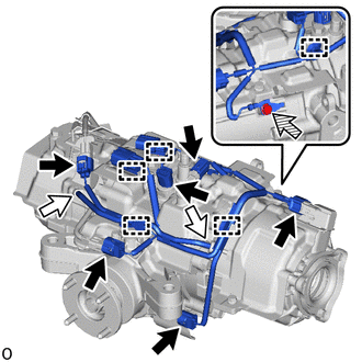
23.INSTALL CLUTCH CONTROL SOLENOID WIRE

|
Connector |

|
Breather Tube |

|
Bolt |
Engage the 5 clamps to install the clutch control solenoid wire.
Install the bolt.
- Torque:
- 5.4 N*m (55 kgf*cm, 48 in.*lbf)
Connect the 6 connectors and 2 breather tubes.