AXLE AND DIFFERENTIAL REAR DIFFERENTIAL CARRIER ASSEMBLY(for Torque Vectoring Differential) DISASSEMBLY
CAUTION / NOTICE / HINT
- NOTICE:
- ·
When replacing the rear drive pinion companion flange and rear differential carrier oil seal, be sure to check the preload.
·If the rear drive pinion companion flange and rear differential carrier oil seal were replaced without checking the preload, replace the torque vectoring differential carrier assembly.
·Before installation of each part, thoroughly clean and dry it. Then apply gear oil to it. Do not use alkaline chemicals to clean aluminum parts, rubber parts or ring gear set bolts. Also, do not use non-residue solvent or other cleaning oils to clean O-rings, oil seals or rubber parts.
PROCEDURE

 31364D
1.REMOVE CLUTCH CONTROL SOLENOID WIRE
31364D
1.REMOVE CLUTCH CONTROL SOLENOID WIRE
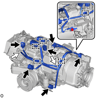

|
Connector |

|
Breather Tube |

|
Bolt |
Disconnect the 6 connectors and 2 breather tubes.
Remove the bolt.
Disengage the 5 clamps to remove the clutch control solenoid wire.
2.REMOVE WIRE HARNESS CLAMP BRACKET
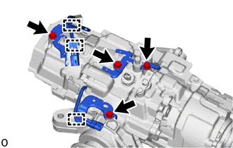
Disengage the 3 clamps.
Remove the 4 bolts and 4 wire harness clamp brackets from the torque vectoring differential carrier assembly.
41173
3.REMOVE DIFFERENTIAL DISCONNECT COVER
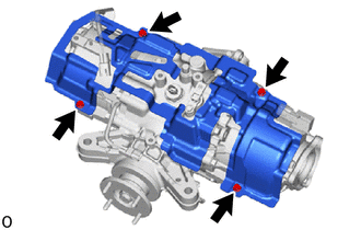
Remove the 4 bolts and differential disconnect cover from the torque vectoring differential carrier assembly.
41173A
4.REMOVE NO. 2 DIFFERENTIAL DISCONNECT COVER
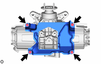
Remove the 4 bolts and No. 2 differential disconnect cover from the torque vectoring differential carrier assembly.
5.INSPECT RUNOUT OF REAR DRIVE PINION COMPANION FLANGE SUB-ASSEMBLY
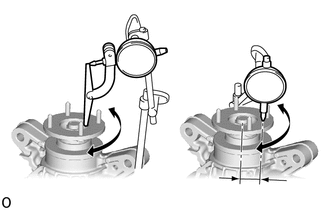
| *a | Vertical Runout |
| *b | Lateral Runout |
| *c | 30 mm (1.18 in.) |
Using a dial indicator, measure the runout of the rear drive pinion companion flange vertical runout and lateral runout.
- Maximum Runout:
Item Specified Condition Vertical runout 0.1 mm (0.00394 in.) Lateral runout 0.1 mm (0.00394 in.)
- NOTICE:
-
Measure the runout of the rear drive pinion companion flange horizontally at a position 50 mm (1.97 in.) away from the center of the differential drive pinion shaft.
- HINT:
-
If the runout is more than the maximum value, replace the rear differential carrier assembly.
6.INSPECT TOTAL PRELOAD
- NOTICE:
- ·
When replacing the rear drive pinion companion flange and rear differential carrier oil seal, be sure to check the preload.
·If the rear drive pinion companion flange and rear differential carrier oil seal were replaced without checking the preload, replace the torque vectoring differential carrier assembly.
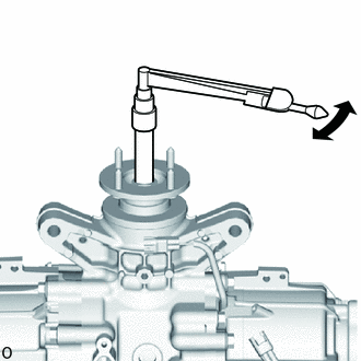
Using a torque wrench, check the starting torque (total preload) with the teeth of the drive pinion and ring gear in contact.
- HINT:
- ·
The torque wrench should be installed as shown in the illustration.
·Record the measured value as it is used during assembly.
·For a more accurate measurement, rotate the bearing forward and backward several times before the measurement.
41204B
7.REMOVE REAR DRIVE PINION NUT
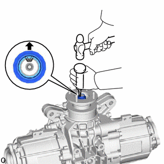
Using a SST and hammer, unstake the rear drive pinion nut.
- SST
- 09930-00010 (09931-00010, 09931-00020)
- NOTICE:
- ·
Completely unstake the rear drive pinion nut.
·Do not damage the threads of the differential gear.
41204
8.REMOVE REAR DRIVE PINION COMPANION FLANGE SUB-ASSEMBLY
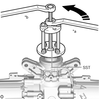
| *a | Turn |
| *b | Hold |
Using SST, remove the rear drive pinion companion flange sub-assembly.
- SST
- 09950-30012 (09951-03010, 09953-03010, 09954-03010, 09955-03030, 09956-03020)
41201C
9.REMOVE REAR DIFFERENTIAL CARRIER OIL SEAL (for Front Side)
41252
10.REMOVE NO. 1 REAR DIFFERENTIAL DUST DEFLECTOR (for LH Side)
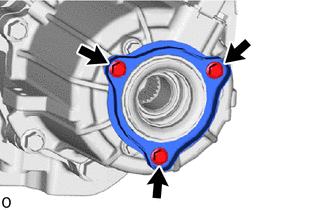
| *1 | No. 1 Rear Differential Dust Deflector |
| *2 | No. 2 Rear Differential Dust Deflector |
Remove the 3 bolts, No. 1 rear differential dust deflector and No. 2 rear differential dust deflector from the electro magnetic control coupling sub-assembly.
41252
11.REMOVE NO. 1 REAR DIFFERENTIAL DUST DEFLECTOR (for RH Side)
- HINT:
-
Perform the same procedure as for the LH side.
12.REMOVE ELECTRO MAGNETIC CONTROL COUPLING SUB-ASSEMBLY (for LH Side)
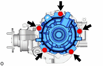
Remove the 5 bolts and electro magnetic control coupling sub-assembly from the rear differential carrier assembly.
Remove the O-ring.
13.REMOVE ELECTRO MAGNETIC CONTROL COUPLING SUB-ASSEMBLY (for RH Side)
- HINT:
-
Perform the same procedure as for the LH side.
41330M
14.REMOVE TRANSMISSION COUPLING DUST SEAL (for LH Side)
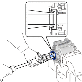
| *1 | Transmission Coupling Dust Seal |
| *a | Cloth |
Secure the electro magnetic control coupling sub-assembly in a vise using aluminum plates and cloths.
- NOTICE:
-
Do not overtighten the vise, as the electro magnetic control coupling sub-assembly may become deformed.
Using SST, remove the transmission coupling dust seal from the electro magnetic control coupling sub-assembly.
- SST
- 09308-00010
41330M
15.REMOVE TRANSMISSION COUPLING DUST SEAL (for RH Side)
- HINT:
-
Perform the same procedure as for the LH side.
16.SECURE TORQUE VECTORING DIFFERENTIAL CARRIER ASSEMBLY
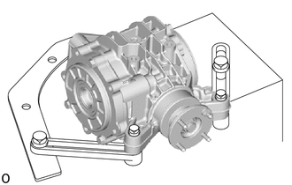
Secure the rear differential carrier assembly to the overhaul attachment.
41110H
17.REMOVE REAR DIFFERENTIAL FILLER PLUG
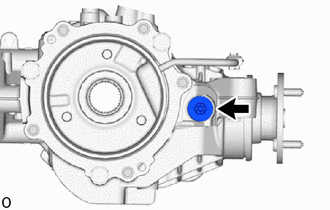
Using a 10 mm socket hexagon wrench, remove the rear differential filler plug and gasket.
41110D
18.REMOVE REAR DIFFERENTIAL DRAIN PLUG
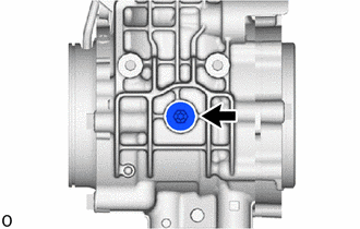
Using a 10 mm socket hexagon wrench, remove the rear differential drain plug and gasket.
41108A
19.REMOVE REAR DIFFERENTIAL CARRIER COVER PLUG
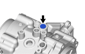
Using an 8 mm socket hexagon wrench, remove the rear differential carrier cover plug.
89413A
20.REMOVE TRANSMISSION REVOLUTION SENSOR
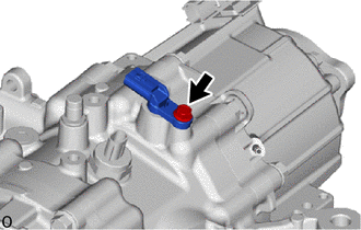
Remove the bolt and transmission revolution sensor from the rear differential carrier assembly.
Remove the O-ring.
84546A
21.REMOVE NO. 2 4 WHEEL DRIVE POSITION SWITCH
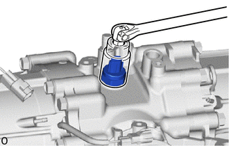
Using SST, remove the No. 2 4 wheel drive position switch from the rear differential carrier assembly.
- SST
- 09816-30010
89429F
22.REMOVE TEMPERATURE SENSOR
41110K
23.REMOVE REAR DIFFERENTIAL BREATHER PLUG
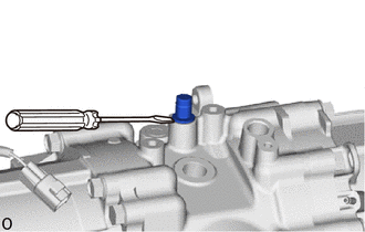
Using a chisel and a hammer, lift the rear differential breather plug slightly.
Using a screwdriver, remove the rear differential breather plug.
41201C
24.REMOVE REAR DIFFERENTIAL CARRIER OIL SEAL (for LH Side)
41201C
25.REMOVE REAR DIFFERENTIAL CARRIER OIL SEAL (for RH Side)